
Double-layer packaging substrate alignment method suitable for laser through hole

A packaging substrate and reference technology, applied in the direction of multilayer circuit manufacturing, electrical connection formation of printed components, etc., can solve the problems of inability to meet high-precision wiring design, reduce the company's cash flow, increase the company's operating burden, etc., to reduce input costs, Meet the design requirements and improve the effect of enterprise cost

Pending Publication Date: 2022-04-15
JIANGSU PROVISION ELECTRONICS CO LTD
View PDF0 Cites 0 Cited by
  • Summary
  • Abstract
  • Description
  • Claims
  • Application Information

AI Technical Summary

Problems solved by technology

In the tenting process, the conventional double-sided board is basically aligned based on the drilled hole, and the alignment between the hole and the graphic will be slightly worse; according to the conventional alignment system design, it can only meet the design of the hole ring > 60um , cannot meet the high-precision wiring design
[0003] With the development trend of electronic products becoming smaller and smaller, the precision requirements of packaging substrates are also getting higher and higher. The introduction of higher-precision equipment will increase the company's fixed assets, virtually reduce the company's cash flow, and increase the company's operating burden.

Method used


Image

  • Double-layer packaging substrate alignment method suitable for laser through hole
  • Double-layer packaging substrate alignment method suitable for laser through hole
  • Double-layer packaging substrate alignment method suitable for laser through hole

Examples


Embodiment

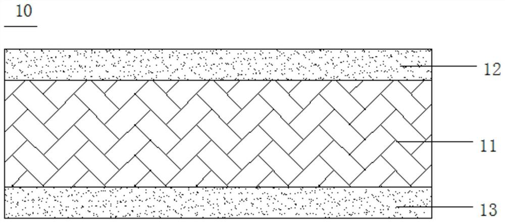
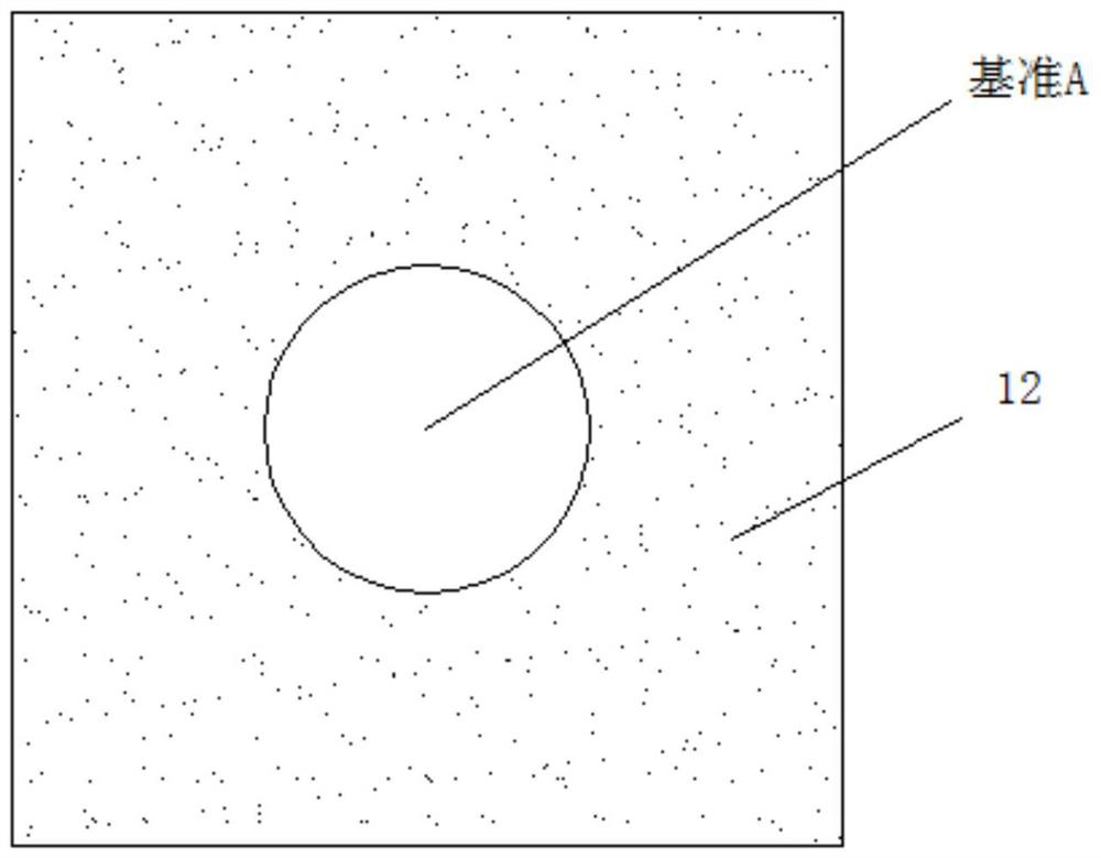
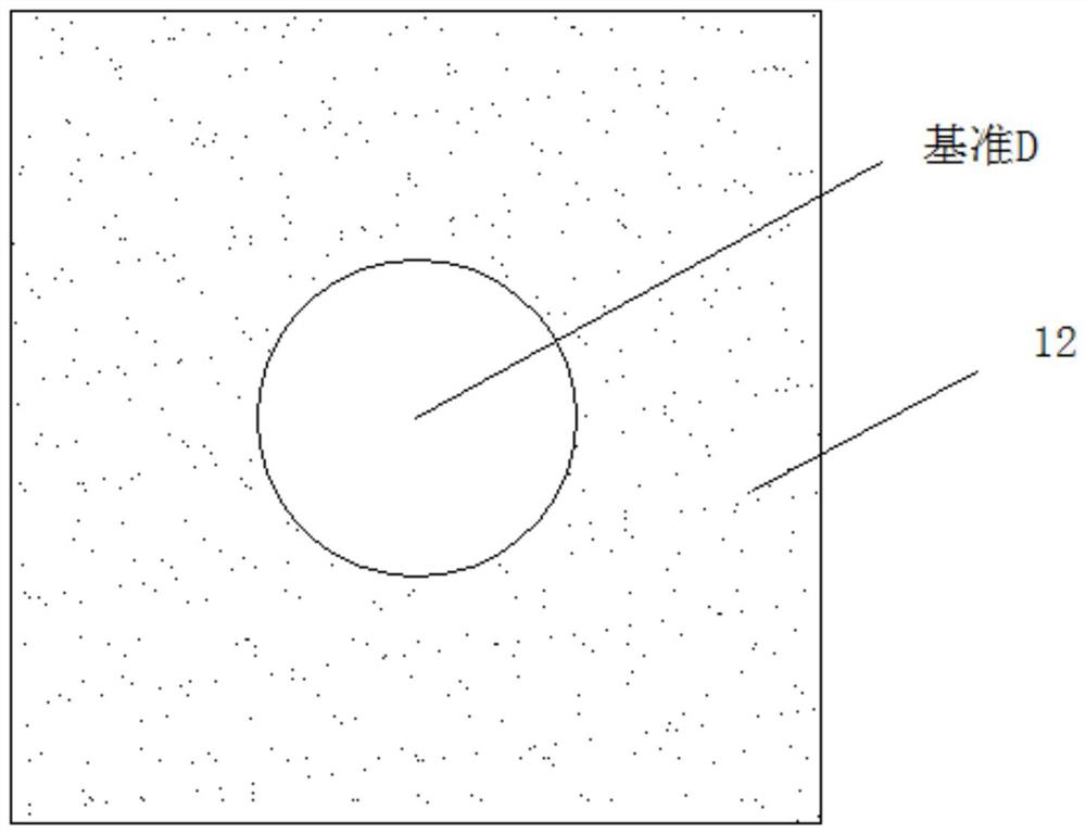
[0047] Example: such as Figure 1-11 As shown, a double-layer packaging substrate alignment method suitable for laser vias includes the following steps:

[0048] Step 1: cutting material: such as figure 1 As shown, a substrate 10 of a certain size is cut, and the substrate has a core layer 11 and a first inner copper foil layer 12 and a second inner copper foil layer 13 respectively arranged on the front and back sides of the core layer;

[0049] Step 2: Mechanical drilling: eg figure 2 and image 3 As shown, using mechanical drilling to make the pre-laser line alignment reference A and the graphic line alignment reference D on the edge of the substrate;

[0050] Step 3: Pre-laser circuit: Based on A, make laser drilling alignment reference B, laser hole opening and line alignment reference C window opening; Figure 4 and Figure 5 shows the windowing of the line-to-bit reference C, Figure 6 Alignment datum B is shown;

[0051] Step 4: Laser drilling: Based on B, make l...


PUM

PropertyMeasurementUnit
Apertureaaaaaaaaaa

Abstract

The invention discloses a double-layer packaging substrate alignment method suitable for laser through holes. The double-layer packaging substrate alignment method comprises the following steps: cutting: cutting a substrate with a certain size; mechanical drilling is conducted, specifically, a line alignment reference A before laser and a pattern line alignment reference D are manufactured; a laser drilling alignment reference B, a laser hole window and a window of a line alignment reference C are manufactured; laser drilling is carried out, wherein a laser via hole in the effective area is manufactured for interlayer conduction, and a line alignment reference C is manufactured; performing copper deposition and electroplating: performing glue residue removal, chemical copper plating and copper electroplating treatment on the laser conduction hole for interlayer conduction and the through hole of the reference C, so that the inner wall of the hole is plated with copper and the interlayer is mutually conducted; and a pattern circuit: when the pattern circuit is manufactured, taking the composite hole fitted by the reference C and the reference D as an alignment reference. Multiple alignment references are involved in the method, and the design requirement that the interlayer alignment degree is smaller than or equal to 25 micrometers is met on the premise that the alignment degree of the patterns on the same layer and the blank is guaranteed.

Description

technical field [0001] The invention relates to a packaging substrate, in particular to a double-layer packaging substrate alignment method suitable for laser through holes. Background technique [0002] At present, there are three mainstream processing technologies for packaging substrates, Tenting masking process, MSAP process, and SAP process, which are three different process systems. In the tenting process, the conventional double-sided board is basically aligned based on the drilled hole, and the alignment between the hole and the graphic will be slightly worse; according to the conventional alignment system design, it can only meet the design of the hole ring > 60um , cannot meet the high-precision wiring design. [0003] With the development trend of electronic products becoming smaller and smaller, the precision requirements of packaging substrates are also getting higher and higher. The introduction of higher-precision equipment will increase the company's fixe...

Claims


Application Information

Patent Timeline
IPC IPC(8): H05K3/46H05K3/42
Inventor 马洪伟宗芯如杨飞
Owner JIANGSU PROVISION ELECTRONICS CO LTD
Learn More