Subcutaneous tumor removing device

A limb and support module technology, which is applied in the field of medical and surgical instruments, can solve the problems of tumor location, depth and shape judgment deviation, no support mechanism for auxiliary support, tumor shape shrinkage, etc., to improve the support effect, facilitate recovery, improve The effect on success rate

Pending Publication Date: 2022-04-19
鄢陵县中医院
0 Cites 0 Cited by

AI-Extracted Technical Summary

Problems solved by technology

[0003] Most of the existing treatment methods are that after the patient is anesthetized, the medical staff lifts the arm to a suitable state, and there is no universal and suitable support mechanism for auxiliary support; in addition, because the fat layer in the armpit is thick, and lipoma is normal It is caused by a large number ...

Abstract

The invention discloses a subcutaneous tumor removing device which comprises a limb supporting module, a tumor limiting module, a connecting module, an arm supporting module and a telescopic ball head rod. The tumor body limiting module is adhered to the outer surface of the skin on the side of an affected limb through a medical adhesive tape along the outer boundary path of the tumor body, and the limb supporting module and the arm supporting module are connected with the tumor body limiting module through telescopic bulb rods. According to the invention, a tumor can be limited and prevented from deforming and displacing when the side body of an affected limb moves, information such as the position, depth and size of the tumor can be accurately judged conveniently, meanwhile, reliable support can be provided for the side body of the affected limb, and the affected part can be completely exposed in the visual field of a doctor in the operation process conveniently; it is guaranteed that the arms on the side of the affected limb and the body are in a separated state during postoperative recovery, and implementation of an operation and recovery of a postoperative suture opening are facilitated.

Application Domain

Operating tablesDiagnostic markers +1

Technology Topic

Visual field lossPostoperative recovery +4

Image

  • Subcutaneous tumor removing device
  • Subcutaneous tumor removing device
  • Subcutaneous tumor removing device

Examples

  • Experimental program(4)

Example Embodiment

[0028] Example 1
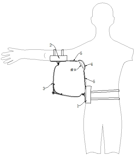
[0029] like Figure 1-7 As shown, a subcutaneous tumor removal device includes a limb support module 1, a tumor limit module 2, a connection module 3, an arm support module 4 and a telescopic ball head rod 5, and the limb support module 1 is connected to the arm through the connection module 3. The support module 4 is connected, the tumor body limiting module 2 is pasted on the outer surface of the skin of the affected limb along the path outside the tumor body by medical adhesive tape, and the limb supporting module 1 and the arm supporting module 4 are connected to the tumor body limiting module 5 through the telescopic ball head rod 5. bit module 2 connection.
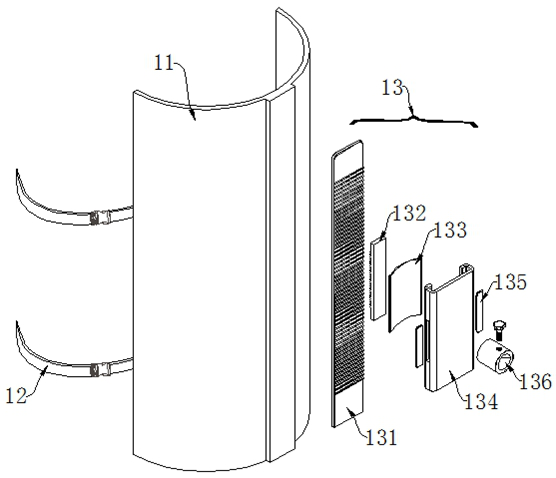
[0030] The limb support module 1 includes a waist support 11, a corset 12 and a first limit mechanism 13. The waist support 11 fits the patient's waist and abdomen through the corset 12, and the lower end of the waist support 11 is connected to the upper end of the hip bone on the side of the affected limb. In case of conflict, the first limiting mechanism 13 is installed on the midline position of the lumbar support 11 away from the side of the body.
[0031] The tumor limiting module 2 includes a limb part 21, a connecting head 22, a sliding part 23 and a fixing seat 24. The limb parts 21 are sequentially connected through the connecting head 22 to form a closed circuit, and the sliding part 23 is installed on the adjacent limb part 21. The junction is slidably connected with the limb part 21 , and the fixing seat 24 is installed on the end surface of the sliding part 23 .
[0032] The connection module 3 includes a support rod 31, a connection box 32, a stopper 33 and an elastic sheet 34. One end of the support rod 31 is connected to the first stop mechanism 13, and the connection between the support rod 31 and the connection box 32 is realized by the stopper 33. Fixedly connected, the elastic piece 34 is installed on the inner end surface of the support rod 31 .
[0033] The arm support module 4 includes an arm support 41, a fixing belt 42 and a second limiting mechanism 43. The arm supporting module 41 fits with the outside of the arm of the patient's affected limb through the fixing belt 42, and the second limiting mechanism 44 is installed under the arm supporting 41. at the midline position of the end face.
[0034] The first limit mechanism 13 includes a fixed tooth plate 131, an engaging tooth plate 132, an elastic card 133, a deck 134, a button 135 and a ball and socket sleeve 136, and the end of the fixed tooth plate 131 is connected to the outside of the arm support 41. The end face is connected, the engaging tooth plate 132 is connected with the fixed tooth plate 131 through the teeth, and the outer end surface of the engaging tooth plate 132 is fixedly connected with the elastic card 133, and the elastic card 133 is installed inside the card holder 134, and through the button 135 The movement is carried out inside the card seat 134 , and the card seat 134 slides outside the fixed tooth plate 131 .
[0035] The tumor body limiting module 2 is fixed at 2 to 3 cm outside the tumor body boundary line.
[0036] There are no less than two telescopic ball studs 5 for connecting the tumor body limiting module 2 and the limb supporting module 1 and between the tumor body limiting module 2 and the arm supporting module 4 .
[0037] The joint part 21 is made of flexible medical rubber material, and the upper end of the joint part 21 is provided with a slot, and the sliding part 23 is engaged outside the slot of the joint part 21 .
[0038] The first limiting mechanism 13 and the second limiting mechanism 44 have the same structure.
[0039]By adopting the above-mentioned technical scheme: when in use, the limbs 21 of the tumor body limiting module 2 are sequentially pasted along the route 2 to 3 cm outside the boundary line of the tumor body, and the limbs 21 are connected end to end to form a closed loop , and take at least two sets of telescopic ball studs 5, and each group is not less than two, so that the telescopic ball studs 5 are arranged in a figure-eight shape. One end of the head rod 5 is fixed, and the lumbar support 11 of the limb support module 1 is attached to the waist and abdomen of the patient's affected limb side, and the lower end of the lumbar support 11 is in conflict with the upper end of the hipbone of the affected limb side, and the lumbar support 11 is secured by using the restraint belt 12. The position of 11 is fixed, the arm support 41 of the arm support module 4 is attached to the outside of the arm of the patient's affected limb through the fixing belt 42, and the arm support 41 is fixed with the fixing belt 42, and the two sets of telescopic ball head rods 5 The other ends of the limb support module 1 and arm support module 4 are respectively connected to the limit mechanism, and the length of the telescopic ball head rod 5 is adjusted, the opening angle of the limiter 33 of the connection module 3 is adjusted, and the two sides of the The end of the support rod 31 is connected with the limit mechanism. When a group of connection modules 3 are used for support, the midlines of the waist support 11 and the arm support 41 are kept in the same plane, so that the connection modules 3 are located in this plane; When a group of connection modules 3 are supported, the connection modules 3 are scattered and arranged, and the opening angle of each stopper 33 can be adjusted according to the lifting angle of the patient's arm. The positioner 33 fits together, thereby the arm of the affected limb side of the patient is held up, so that the patient's armpit is exposed, which is convenient for performing the operation and is conducive to the recovery of the postoperative wound.

Example Embodiment

[0040] Example 2
[0041] like figure 1 , Image 6 and Figure 7 As shown, a subcutaneous tumor removal device includes a limb support module 1, a tumor limit module 2, a connection module 3, an arm support module 4 and a telescopic ball head rod 5, and the limb support module 1 is connected to the arm through the connection module 3. The support module 4 is connected, the tumor body limiting module 2 is pasted on the outer surface of the skin of the affected limb along the path outside the tumor body by medical adhesive tape, and the limb supporting module 1 and the arm supporting module 4 are connected to the tumor body limiting module 5 through the telescopic ball head rod 5. bit module 2 connection.
[0042] The limb support module 1 includes a waist support 11, a corset 12 and a first limit mechanism 13. The waist support 11 fits the patient's waist and abdomen through the corset 12, and the lower end of the waist support 11 is connected to the upper end of the hip bone on the side of the affected limb. In case of conflict, the first limiting mechanism 13 is installed on the midline position of the lumbar support 11 away from the side of the body.
[0043] The connection module 3 includes a support rod 31, a connection box 32, a stopper 33 and an elastic sheet 34. One end of the support rod 31 is connected to the first stop mechanism 13, and the connection between the support rod 31 and the connection box 32 is realized by the stopper 33. Fixedly connected, the elastic piece 34 is installed on the inner end surface of the support rod 31 .
[0044] The arm support module 4 includes an arm support 41, a fixing belt 42 and a second limiting mechanism 43. The arm supporting module 41 fits with the outside of the arm of the patient's affected limb through the fixing belt 42, and the second limiting mechanism 44 is installed under the arm supporting 41. at the midline position of the end face.
[0045] By adopting the above technical scheme: during the operation, the patient can adopt a lying position or a side lying position. When the patient adopts a lying position, the side of the affected limb can be raised with a soft pad. After the patient is anesthetized, the patient can be placed Lift the arm on the side of the limb to the outside, so that the armpit on the side of the affected limb is fully exposed, and the connection module 3 can be rotated along the vertical direction of the midline plane of the lumbar support 11 and the arm support 41, so that the connection box 32 is close to the operating table, and connected The contact point between the box 32 and the operating table is a supporting point, which supports the inclined affected limb, not only can fully expose the affected part, but also can reliably support the limb to facilitate the operation; when the patient takes a lateral position, Take two groups of connection modules 3, and make the connection modules 3 symmetrically distributed, so that the connection boxes 32 on both sides are in contact with the operating table, and use the contact point as a support point. After the affected limb is lifted, the forearm of the affected limb is used The auxiliary equipment is supported, and the upper arm of the affected limb is supported through the connection module 3 . When the patient is in the recovery period, the connection modules 3 are symmetrically distributed on both sides of the midline plane of the lumbar support 11 and the arm support 41, the weight of the arm of the affected limb is transmitted to the lumbar support 41 by the support rod 31, and the support rod 31 and the connection box 32 is connected to the inner end surface of one end and the stopper 33, so that the angle between the support rods 31 cannot be further reduced. When the arm on the side of the affected limb is lifted to a certain angle, the support rod 31 rotates to the outer end face and collides with the connection box 32. At this time, the angle between the support rods 31 reaches the maximum, and the arm on the affected limb cannot Continue to lift up, so that the range of motion of the arm on the affected limb can be limited, and excessive movement of the affected limb can be prevented from causing the suture opening to rupture.

Example Embodiment

[0046] Example 3
[0047] like figure 1 , image 3 , Figure 4 and Figure 5 As shown, a subcutaneous tumor removal device includes a limb support module 1, a tumor limit module 2, a connection module 3, an arm support module 4 and a telescopic ball head rod 5, and the limb support module 1 is connected to the arm through the connection module 3. The support module 4 is connected, the tumor body limiting module 2 is pasted on the outer surface of the skin of the affected limb along the path outside the tumor body by medical adhesive tape, and the limb supporting module 1 and the arm supporting module 4 are connected to the tumor body limiting module 5 through the telescopic ball head rod 5. bit module 2 connection.
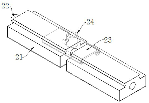
[0048] The tumor limiting module 2 includes a limb part 21, a connecting head 22, a sliding part 23 and a fixing seat 24. The limb parts 21 are sequentially connected through the connecting head 22 to form a closed circuit, and the sliding part 23 is installed on the adjacent limb part 21. The junction is slidably connected with the limb part 21 , and the fixing seat 24 is installed on the end surface of the sliding part 23 .
[0049] The tumor body limiting module 2 is fixed at 2 to 3 cm outside the tumor body boundary line.
[0050] The joint part 21 is made of flexible medical rubber material, and the upper end of the joint part 21 is provided with a slot, and the sliding part 23 is engaged outside the slot of the joint part 21 .
[0051] By adopting the above-mentioned technical scheme: before the operation, use melanin solution to mark the swelling boundary of the tumor body, attach the limbs 21 of the tumor body limiting module 2 sequentially along the route 2 to 3 cm outside the tumor body boundary line, and The limbs 21 are connected end to end to form a closed circuit. When the boundary line of the tumor mass is a regular circle, and the boundaries are all in the same plane, determine the number of joints 21 required by calculating the perimeter of the boundary, and bend each joint 21 at the same angle Insert the connecting head 22 fixed with the joint part 21 into the ball hole at the end of the joint part 21, and then connect the joint parts 21 head to tail in turn, so that the joint part 21 is surrounded into a closed ring shape, so that The inner diameter of the ring is 2 to 3 cm outside the marked boundary, and each limb joint 21 can be attached to the outer skin of the affected limb with medical tape. When the boundary line of the tumor mass is irregular in shape, and the boundary line is distributed in a high and low staggered manner, determine the number of joints of the required limbs 21 by calculating the boundary perimeter, and adjust the corresponding limbs according to the curvature at the corner of the marked boundary line. The degree of bending of the joint 21 makes the joint 21 attached at this position fit the marked boundary, and when the joint 22 is connected to the joint 21, the joint 22 can be freely inside the joint 21. Rotate so that two adjacent joints 21 can be in different planes, and at the same time can be inclined at a certain angle, so as to be suitable for tumors with irregular boundaries. After the limb part 21 is fixed, the telescopic ball head rod 5 is connected to the limb support module 1 and the arm support module 4 respectively, so that the tumor body can be limited. The internal movement of the closed area surrounded by 21 can prevent the displacement of the tumor body, reduce the degree of deformation of the tumor body at the same time, and facilitate the judgment of the size, position and growth depth of the tumor body.

PUM

no PUM

Description & Claims & Application Information

We can also present the details of the Description, Claims and Application information to help users get a comprehensive understanding of the technical details of the patent, such as background art, summary of invention, brief description of drawings, description of embodiments, and other original content. On the other hand, users can also determine the specific scope of protection of the technology through the list of claims; as well as understand the changes in the life cycle of the technology with the presentation of the patent timeline. Login to view more.

Similar technology patents

An improvement method for mission success rate of mobile terminal

ActiveCN101217814Aincrease success rateAvoid cell reselection
Owner:SPREADTRUM COMM (SHANGHAI) CO LTD

Method for dynamic channel selection

InactiveCN101765118AImprove system resource utilizationincrease success rate
Owner:TD TECH COMM TECH LTD

Classification and recommendation of technical efficacy words

  • reliable support
  • increase success rate

Oil paper insulation early stage discharge defect diagnosis method

InactiveCN102207532Areliable support
Owner:STATE GRID CORP OF CHINA +2

Checking device

InactiveCN104931511Areliable support
Owner:HITACHI INFORMATION & CONTROL SOLUTIONS LTD

Etching apparatus

InactiveCN106065475AImprove efficiencyreliable support
Owner:朴锺模

Electronic device

PendingCN112671955ASimple structurereliable support
Owner:GUANGDONG OPPO MOBILE TELECOMM CORP LTD

Vertical type air conditioner

ActiveCN103032943AImprove overall connectivityreliable support
Owner:GREE ELECTRIC APPLIANCES INC OF ZHUHAI

Tissue ablation device and method of use

InactiveUS6855144B2increase success rateeliminate processing
Owner:RGT UNIV OF CALIFORNIA

Residing target selection method and transmission method and device

InactiveCN107197486Aincrease success rateReduce air interface signaling overhead and terminal energy consumption
Owner:ZTE CORP

D-shaped invasive prosthetic heart valve

ActiveCN105520792Aincrease success rate
Owner:SHANGHAI NEWMED MEDICAL CO LTD
Why Eureka
Try Eureka