Eureka AIR delivers breakthrough ideas for toughest innovation challenges, trusted by R&D personnel around the world.

Material filtering and supporting structure in spray drying tower, production equipment and process of material filtering and supporting structure

A technology of spray drying tower and support structure, which is applied in the direction of drying solid materials, spray evaporation, and dispersed particle filtration, etc., which can solve the problems of poor use effect and achieve the effect of ensuring use effect, ensuring position stability and angle stability

Active Publication Date: 2022-04-19
HUBEI JIANGYUAN CHEM MACHINERY
View PDF6 Cites 0 Cited by
  • Summary
  • Abstract
  • Description
  • Claims
  • Application Information

AI Technical Summary

Problems solved by technology

[0005] The object of the present invention is to provide material filtration support structure, production equipment and technology in the spray drying tower, aiming to solve the problem of poor use effect

Method used


Image

  • Material filtering and supporting structure in spray drying tower, production equipment and process of material filtering and supporting structure
  • Material filtering and supporting structure in spray drying tower, production equipment and process of material filtering and supporting structure
  • Material filtering and supporting structure in spray drying tower, production equipment and process of material filtering and supporting structure

Examples


Embodiment Construction

[0065] The technical solution of the present invention will be clearly and completely described below in conjunction with the accompanying drawings and specific embodiments. Apparently, the described embodiments are only some of the embodiments of the present invention, not all of them. Based on the embodiments of the present invention, all other embodiments obtained by persons of ordinary skill in the art without creative efforts fall within the protection scope of the present invention.

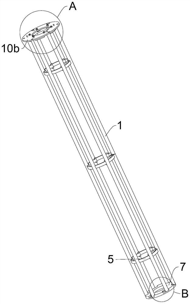
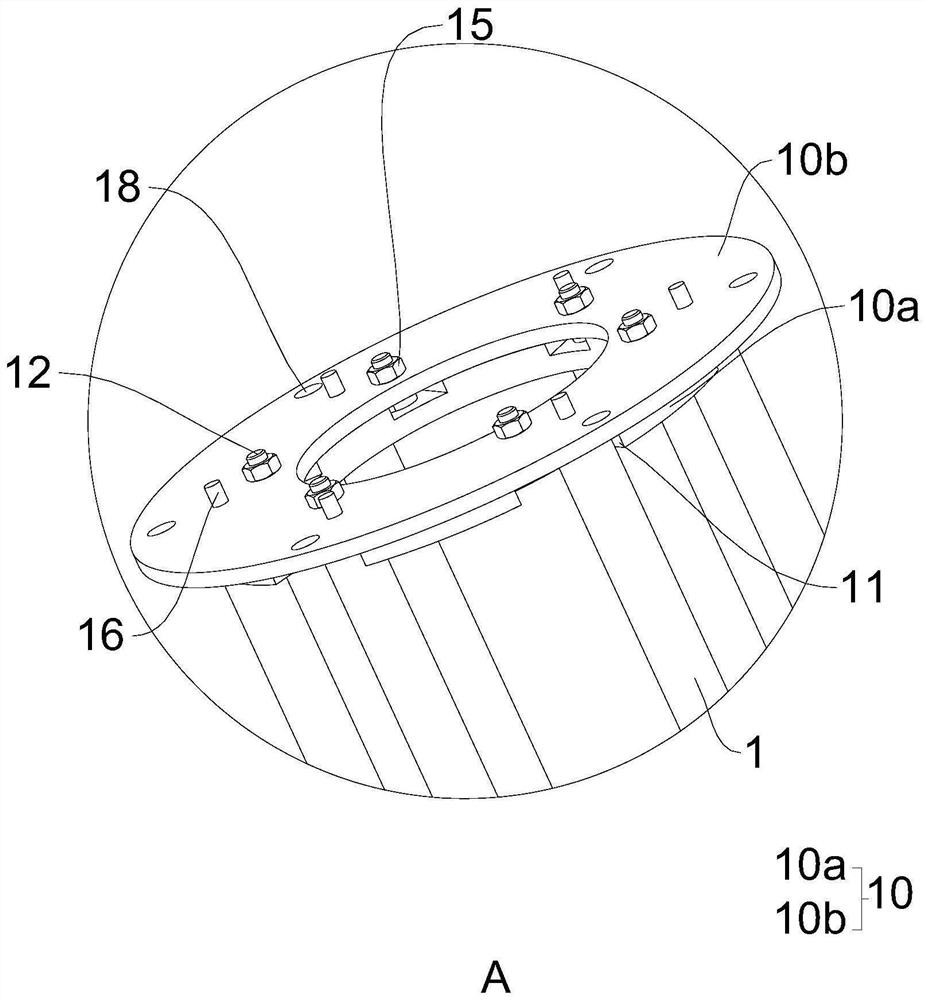
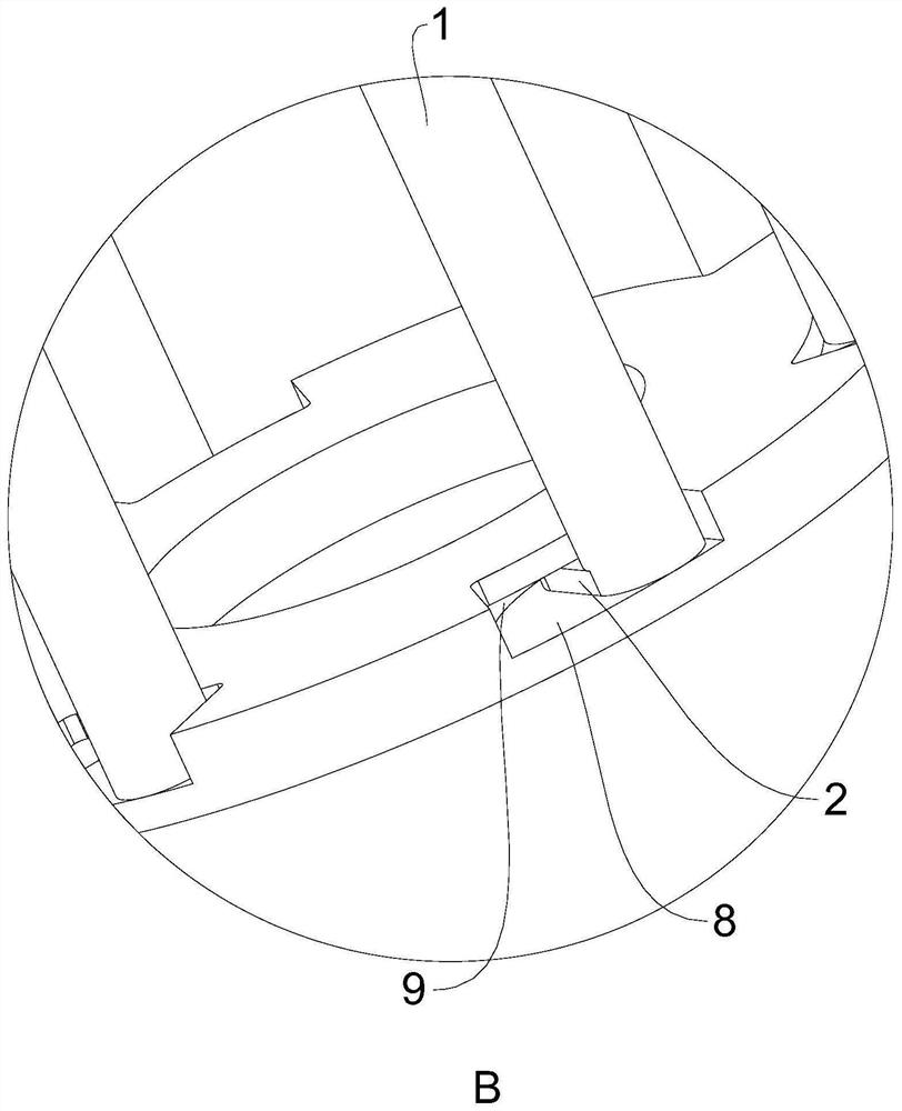
[0066] A material filtering support structure in a spray drying tower, such as Figure 1 to Figure 11 shown, including,

[0067] Several cylindrical support rod bodies 1, the two ends of the support rod body 1 are respectively provided with a first connecting body 2 and a second connecting body 3 perpendicular to the supporting rod body 1, and on the outer wall of the supporting rod body 1 There are several pairs of limit blocks 4;

[0068] Several support rings 5, the outer walls of the...


PUM


Abstract

The invention relates to the technical field of spray drying, and discloses a material filtering and supporting structure in a spray drying tower, the material filtering and supporting structure comprises a plurality of supporting rod bodies, a first connecting body and a second connecting body which are perpendicular to the supporting rod bodies are arranged at the two ends of the supporting rod bodies respectively, and a plurality of pairs of limiting blocks are arranged on the outer walls of the supporting rod bodies; a plurality of matching grooves matched with the outer wall of the supporting rod body are formed in the outer wall of each supporting ring, and each supporting ring is clamped between the corresponding two limiting blocks which are oppositely arranged; a plurality of containing grooves are formed in the periphery of the top of the first connecting ring, clamping grooves matched with the containing grooves are formed in the side walls of the containing grooves, the tops of the clamping grooves are lower than the top of the first connecting ring, the bottom end of each supporting rod body is located in the corresponding containing groove, and each first connecting body is clamped in the corresponding clamping groove; and the second connecting ring is fixedly connected with the tops of all the supporting rod bodies. According to the invention, the use effect is better.

Description

technical field [0001] The invention relates to the technical field of spray drying, in particular to a material filtering support structure in a spray drying tower, production equipment and a process thereof. Background technique [0002] Spray drying is a method of systematic technology applied to material drying. After the thinner is atomized in the drying room, the water vaporizes quickly in contact with the hot air, and the dry product is obtained. This method can directly dry the solution and emulsion into powder or granular products, which can save the evaporation, crushing and other processes. [0003] At present, common spray drying equipment mainly includes air filter (filtering impurities and pollutants in the air), heater (used to filter air), drying chamber, high-speed centrifugal atomizer, mother liquor tank, cyclone dust collector , bag dust collector, etc.; during spray drying, the mother liquor in the mother liquor tank is centrifugally atomized by the hig...

Claims


Application Information

Patent Timeline
Patent Type & Authority Applications(China)
IPC IPC(8): B01D1/18B01D1/30B01D46/06B01D46/42F26B17/10F26B25/00
CPCB01D1/18B01D1/30B01D46/06B01D46/4227F26B17/10F26B25/00
Inventor 彭高吕志虎
Owner HUBEI JIANGYUAN CHEM MACHINERY
Why Eureka
Eureka Blog
Learn More