

Belts and Belt Drives
A technology of belt transmission and belts, which is applied in the direction of transmission devices, belts/chains/gears, V-shaped belts, etc., can solve the problem of reducing the supporting surface of the belt and achieve the effect of low friction
- Summary
- Abstract
- Description
- Claims
- Application Information
AI Technical Summary
Problems solved by technology
Method used
Image

Examples
Embodiment Construction
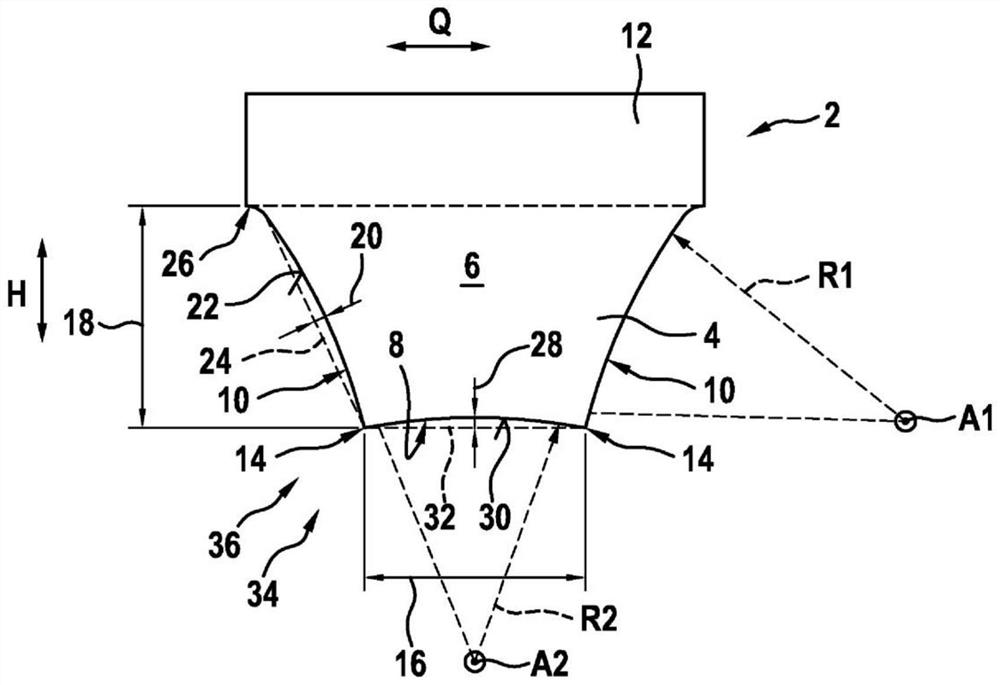
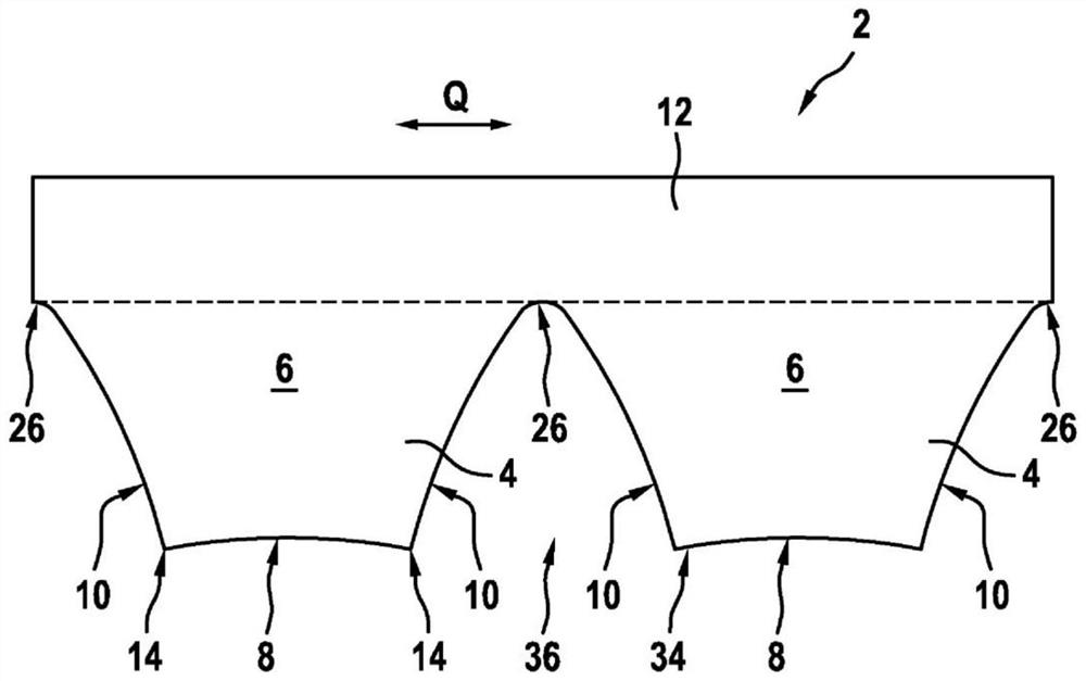
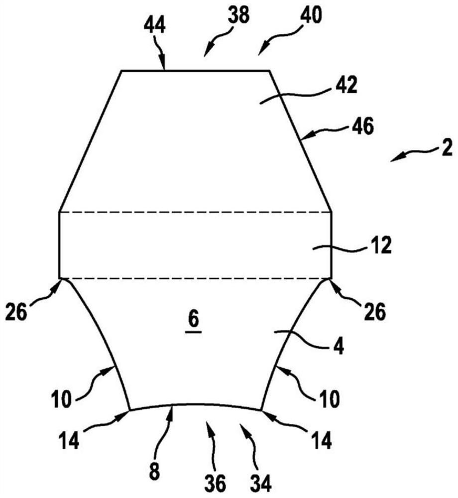
[0032] exist figure 1 The belt 2 is shown in a schematic cross-sectional view. The belt 2 has at least one rib 4 , also referred to as first rib 4 . The first rib 4 extends in the belt longitudinal direction. This is for example from Figure 4 available. Each first rib 4 has an at least substantially trapezoidal cross-section 6 . Due to the trapezoidal cross-sectional shape, each first rib 4 therefore has a support side 8 and two side faces 10 extending from the support side 8 . The supporting side 8 of the first rib 4 likewise extends in the longitudinal direction L of the belt. Each side face 10 of the first rib 4 also extends in the longitudinal direction L of the belt. Preferably, the trapezoidal cross-section 6 of each first rib 4 is formed symmetrically with respect to the side face 10 . Thus, the side faces 10 of the individual first ribs 4 are arranged symmetrically to one another. Furthermore, it is preferably provided that the respective side surfaces 10 of t...
PUM
| Property | Measurement | Unit |
|---|---|---|
| diameter | aaaaa | aaaaa |
| diameter | aaaaa | aaaaa |
Abstract
Description
Claims
Application Information