
Discharge lamp, and method for the production of such a discharge lamp

A discharge lamp and lamp holder technology, applied in the manufacture of discharge tubes/lamps, discharge lamps, electrode systems, etc., can solve problems such as deformation of welding points and fixed connection plates, and achieve reduction of plastic deformation, simple bending resistance- and torsional stiffness, mechanical stress reduction effect

Inactive Publication Date: 2012-05-23
OSRAM GMBH
View PDF5 Cites 2 Cited by
  • Summary
  • Abstract
  • Description
  • Claims
  • Application Information

AI Technical Summary

Problems solved by technology

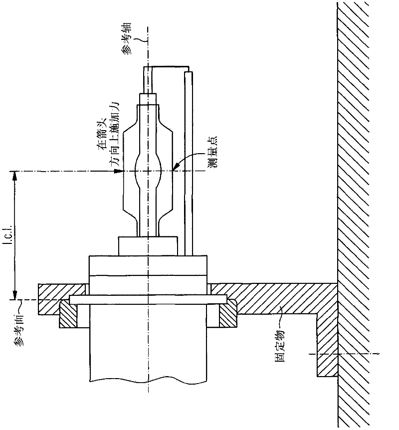
[0005] Disadvantages of the aforementioned discharge lamps are that the welding points and the fastening webs are highly plastically deformed, especially when the lamp vessel is subjected to transverse loads

Method used


Image

  • Discharge lamp, and method for the production of such a discharge lamp
  • Discharge lamp, and method for the production of such a discharge lamp
  • Discharge lamp, and method for the production of such a discharge lamp

Examples


Embodiment Construction

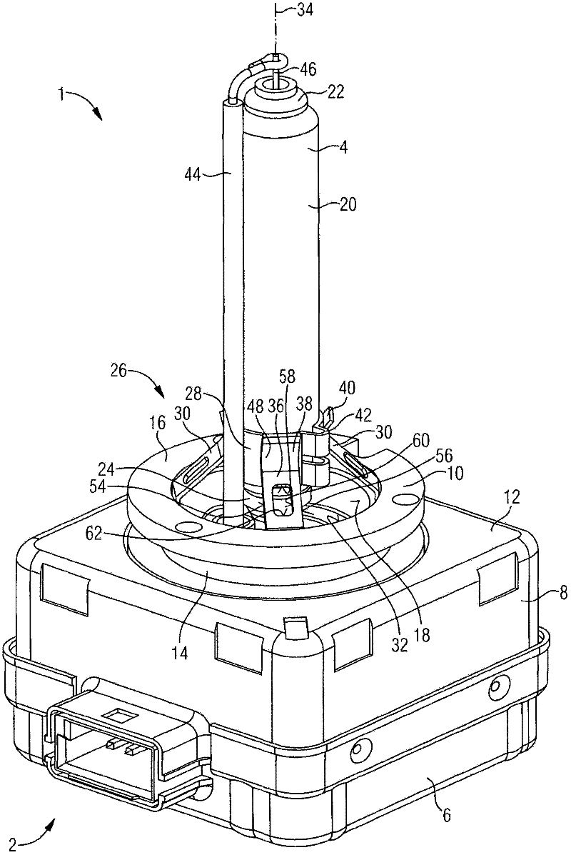
[0030] in figure 2 A perspective view of the discharge lamp 1 according to the first embodiment is shown in. This refers to a high-pressure discharge lamp that can be used as a D-lamp in vehicle lighting, especially as a D1-, D2-, D3-, or D4-lamp. The discharge lamp 1 has a lamp vessel 4 made of quartz glass, which is fixed by a multi-part metal socket 2 and has electrodes arranged therein for causing a gas discharge. The lamp holder 2 is basically constructed in a square shape, with an upper part of the holder and a lower part 6, 8 of the holder. A substantially cylindrical socket element 10 is installed in the top surface 12 of the upper part 8 of the lamp holder, and the lamp housing 4 is fixed by the element. The socket element 10 has an annular connecting piece 14 extending away from the top surface 12, and the retaining ring 16 is designed on the connecting piece as a component of a bayonet connection for fixing the discharge lamp 1 in a vehicle lighting lamp, for examp...


PUM

PropertyMeasurementUnit
Thicknessaaaaaaaaaa
Widthaaaaaaaaaa
Thicknessaaaaaaaaaa

Abstract

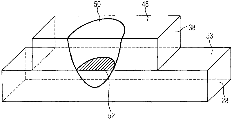
A discharge lamp is disclosed, comprising a bulb that is mounted on a base. Four metal fastening brackets which are arranged in an approximately regular fashion around a longitudinal axis of the lamp and are offset relative to each other protrude from the base. Said fastening brackets are welded to a metal clamp which firmly embraces the base. Each fastening bracket has a holding section and an adjacent welded section. A welded cross-section in a joining plane located between the metal clamp and the welded section has a minimum area of 0.5 mm2, and / or the holding section has at least one recess.

Description

Technical field [0001] The present invention relates to a discharge lamp according to the preamble of claim 1, in particular a D-lamp (double spiral filament lamp), and a discharge lamp according to the preamble of claim 11 的制造方法。 Manufacturing method. Background technique [0002] The patent document DE 10 2006 042 178 A1 discloses such a discharge lamp, which is used in vehicle lighting. This type of discharge lamp has a lamp holder, which includes a lamp holder having a substantially circular cross-sectional gap, and the lamp housing is inserted into the gap section by section. Four metal fixing connecting plates evenly distributed around the gap of the lamp holder protrude from the lamp holder for holding. A welding point is used to weld the fixed connecting plate to an end face section allocated to the lamp holder and fixedly surround the lamp housing, thereby mechanically connecting the lamp housing and the lamp holder. [0003] During use, the discharge lamp is subjected t...

Claims


Application Information

Patent Timeline
IPC IPC(8): H01J5/48H01J5/56H01J9/30
CPCH01J5/56H01J5/48H01J9/30
Inventor 基利安·克拉格斯卡斯滕·皮奇弗洛里安·贝迪内克
Owner OSRAM GMBH
Learn More