
Belt and belt drive

A belt drive, belt technology, applied in the belt drive, belt field, can solve the problem of reducing the belt support surface and so on

Active Publication Date: 2020-07-10
CONTITECH ANTRIEBSSYST
View PDF7 Cites 0 Cited by
  • Summary
  • Abstract
  • Description
  • Claims
  • Application Information

AI Technical Summary

Problems solved by technology

Finally, this configuration also poses the risk of a relatively reduced bearing surface for the belt

Method used


Image

  • Belt and belt drive
  • Belt and belt drive
  • Belt and belt drive

Examples


Embodiment Construction

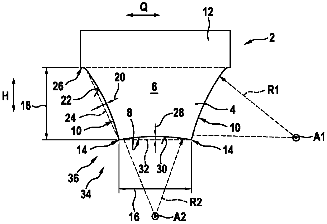
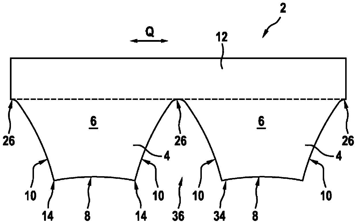
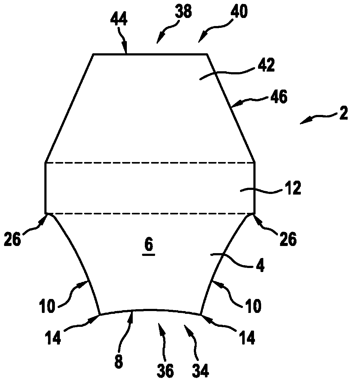
[0032] exist figure 1 The belt 2 is shown in a schematic cross-sectional view. The belt 2 has at least one rib 4 , also referred to as first rib 4 . The first rib 4 extends in the belt longitudinal direction. This is for example from Figure 4 available. Each first rib 4 has an at least substantially trapezoidal cross-section 6 . Due to the trapezoidal cross-sectional shape, each first rib 4 therefore has a support side 8 and two side faces 10 extending from the support side 8 . The supporting side 8 of the first rib 4 likewise extends in the longitudinal direction L of the belt. Each side face 10 of the first rib 4 also extends in the longitudinal direction L of the belt. Preferably, the trapezoidal cross-section 6 of each first rib 4 is formed symmetrically with respect to the side face 10 . Thus, the side faces 10 of the individual first ribs 4 are arranged symmetrically to one another. Furthermore, it is preferably provided that the respective side surfaces 10 of t...


PUM


Abstract

The present invention relates to a belt (2), having: at least one rib (4) formed in the belt longitudinal direction L, wherein each rib (4) has a trapezoidal cross-section (6) and each rib (4) therefore has a contact side (8) and two flanks (10) extending from the contact side (8), characterised in that each flank (10) is curved inwardly and / or each contact side (8) is curved inwardly. The invention also relates to a belt drive having a belt (2) of this kind and at least one belt pulley.

Description

technical field [0001] The invention relates to a belt and a belt transmission device. Background technique [0002] In principle, belts are known from the prior art. By "belt" is understood the belt itself or the traction means (in particular a belt-type traction means). The belt can thus be formed, for example, as a belt belt or as a belt. The belt can be designed, for example, as a V-belt or as a V-ribbed belt. In order to transmit the tractive force to the V-belt, the running surface of the trapezoid is brought into engagement with the drive pulley, so that the V-belt winds around the drive pulley at a defined winding angle. In this case, the force between the V-belt and the drive pulley acts on the contact surface between the V-belt and the drive pulley. In this case, the drive pulley can have a cylindrical support ring section and two retaining rings which are arranged on opposite end sides of the support ring section. In this configuration of the drive pulley, co...

Claims


Application Information

Patent Timeline
IPC IPC(8): F16G5/06F16G5/20
CPCF16G5/06F16G5/20F16H7/02
Inventor 胡贝特·格泽安德烈·库哈尔奇克扬-亨宁·夸斯
Owner CONTITECH ANTRIEBSSYST
Learn More