
Eureka
For R&D, Eureka makes reading and utilizing patents & technical documents easy.
Eureka AIR
Designed for self-driven R&D workflows. Generate viable solutions, solve complex R&D challenges, empower your innovation with AI.

Eureka Materials
Designed for material experts only. Revolutionize your material R&D, from search, analyze, to developing new materials.

TechResearch
Generate reliable direction feasibility study reports for your R&D in just a few steps.

TechSeek
Discover and master advanced knowledge NOW. Basics, ideas, possibilities, all at once.

TechMind
As an expert in R&D Theories, TechMind can generates customized viable solutions instantly.

TechRisk
Analyze your overall solution with one click, know your potential R&D risks in advance.

TechMonitor
Get weekly tech updates, stay abreast of the latest tech innovations and key insights.
Anesthesia breathing circuit heating device and anesthesia machine with anesthesia breathing circuit heating device
A breathing circuit and heating device technology, applied in the field of anesthesia machines, can solve problems such as poor heating effect of the loop tube, influence on the performance of the anesthesia machine, influence on the overall performance of the anesthesia machine, etc.
- Summary
- Abstract
- Description
- Claims
- Application Information
AI Technical Summary
Problems solved by technology
Method used
Image

Examples
Embodiment 1
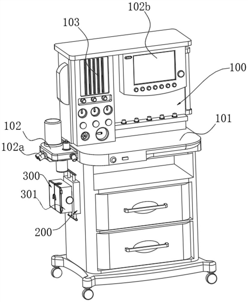
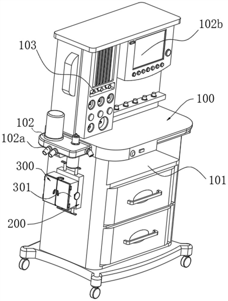
[0032] refer to Figure 1~6 , which is the first embodiment of the present invention, provides an anesthesia breathing circuit heating device and an anesthesia machine with the component, the anesthesia breathing circuit heating device and the anesthesia machine with the component include a main unit 100, including an anesthesia machine 101, The ventilator 102 arranged on the surface side of the anesthesia machine 101, the monitor 103 arranged on the top of the anesthesia machine 101; and,
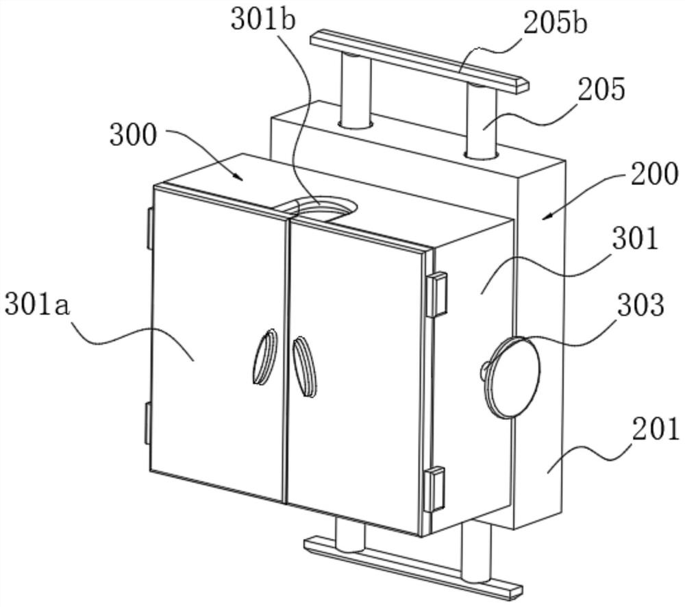
[0033] The disassembly unit 200 is arranged on one side of the surface of the anesthesia machine 101, including a fixed bin 201, which is arranged on a fixed block 204 on the side of the fixed bin 201 away from the anesthesia machine 101, and the fixed block 204 extends to the inner cavity of the fixed bin 201. The limit rods 202 at the top and bottom of the inner cavity of the fixed warehouse 201, the two sets of first sets of blocks 203 arranged on the outer walls of the limit rod 202, t...
Embodiment 2
[0038] refer to Figure 1~6 , is the second embodiment of the present invention, which is based on the previous embodiment.
[0039] Preferably, the limit rod 202 further includes a spring 202a, which is arranged on the top and bottom of the outer wall of the limit rod 202. By setting the spring 202a, the elastic force of the spring 202a can be used to drive the insertion rod 205 to reset and fix automatically.
[0040] Preferably, the insertion rod 205 also includes a stopper 205a and a pull rod 205b, the stopper 205a arranged on the outer wall of the inner cavity of the insertion rod 205 located at the fixed bin 201, and the pull rod 205b arranged at the outer end of the inserted rod 205 at the outer end of the fixed bin 201, through The setting of 20b can simultaneously pull two sets of insertion rods 205, which is convenient for fixed installation.
[0041] Specifically, the first set block 203 further includes connecting blocks 203a, which are arranged on both sides of t...
Embodiment 3
[0045] refer to Figure 1~6 , is the third embodiment of the present invention, and this embodiment is based on the first two embodiments.
[0046] Specifically, the fixing block 204 also includes a fixing hole 204a, which is arranged at the top and bottom of the fixing block 204, and the insertion rod 205 passes through the fixing hole 204a.
[0047] Preferably, the fixed bin 201 also includes a fixed port 201a, which is arranged at the end of the fixed bin 201 away from the surface of the anesthesia machine 101. The number of fixed ports 201a is four groups, and corresponds to the fixed block 204 one by one. The fixed block 204 passes through the fixed port. The port 201a extends to the inner cavity of the fixed bin 201 .
[0048] Preferably, the positioning block 306 further includes a positioning groove 306a, which is arranged at one end of the positioning block 306, and the setting of the positioning groove 306a is convenient for limiting and fixing the circuit pipe.
...
PUM
 Abstract
Description
Claims
Application Information
 - R&D Engineer
- R&D Manager
- IP Professional
- Industry Leading Data Capabilities
- Powerful AI technology
- Patent DNA Extraction
Browse by: Latest US Patents, China's latest patents, Technical Efficacy Thesaurus, Application Domain, Technology Topic, Popular Technical Reports.
© 2024 PatSnap. All rights reserved.Legal|Privacy policy|Modern Slavery Act Transparency Statement|Sitemap|About US| Contact US: help@patsnap.com