Heavy-load pneumatic chuck for laser pipe cutting machine

A technology for carrying pneumatic clamps and pipe cutting machines. It is applied in laser welding equipment, applications, tubular objects, etc. It can solve problems such as loosening and clamping effects, and achieve the effects of reducing transmission resistance, avoiding workpiece deformation, and improving transmission efficiency.

Pending Publication Date: 2022-04-22
JIANGSU YAWEI MACHINE TOOL
View PDF6 Cites 0 Cited by
  • Summary
  • Abstract
  • Description
  • Claims
  • Application Information

AI Technical Summary

Problems solved by technology

There is also a large gap between the two opening and closing levers that drive the jaws, which may loosen during movement, which has a great impact on the clamping effect

Method used


Image

  • Heavy-load pneumatic chuck for laser pipe cutting machine
  • Heavy-load pneumatic chuck for laser pipe cutting machine
  • Heavy-load pneumatic chuck for laser pipe cutting machine

Examples


Embodiment Construction

[0029] The technical solutions of the present invention will be further described below in conjunction with the accompanying drawings and through specific implementation methods.

[0030] Wherein, the accompanying drawings are only for illustrative purposes, showing only schematic diagrams, rather than physical drawings, and should not be construed as limitations on this patent; in order to better illustrate the embodiments of the present invention, some parts of the accompanying drawings will be omitted, Enlargement or reduction does not represent the size of the actual product; for those skilled in the art, it is understandable that certain known structures and their descriptions in the drawings may be omitted.

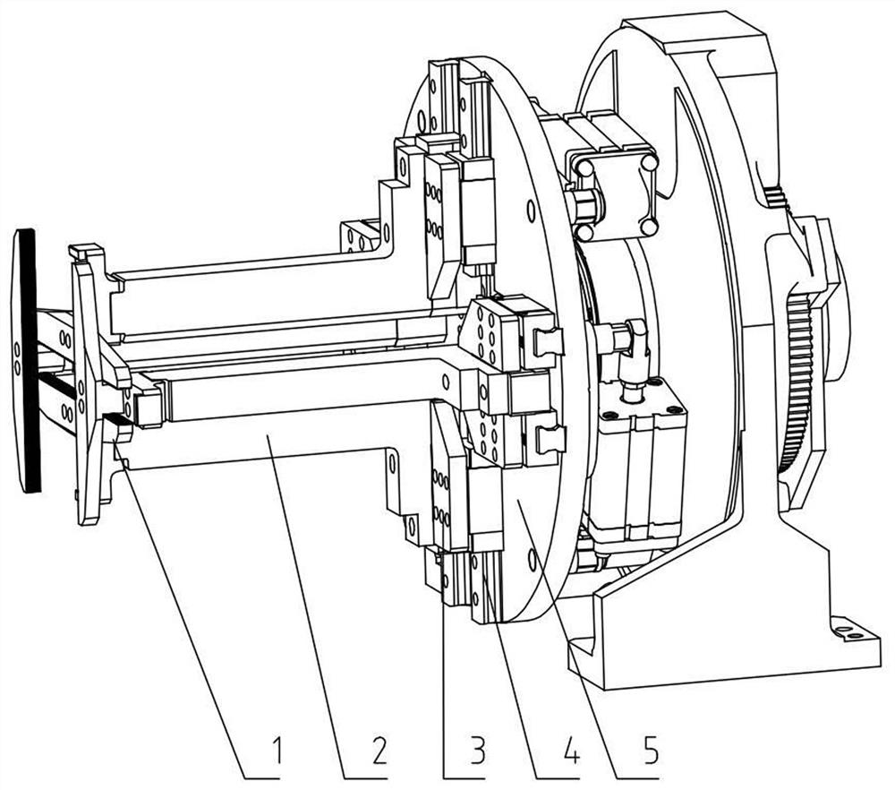
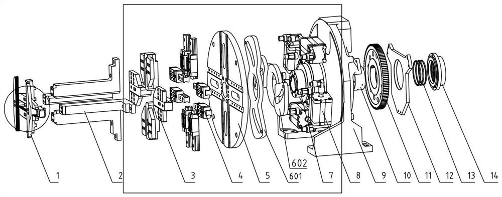
[0031] The invention provides a technical solution: as figure 2 As shown, a heavy-duty pneumatic chuck for a laser pipe cutting machine includes a base 9 and a rotating main shaft 10, the base 9 and the rotating main shaft 10 are slidingly connected, and the rotati...


PUM


Abstract

The invention discloses a heavy-load pneumatic chuck for a laser pipe cutting machine, and relates to the technical field of pneumatic chucks. The device comprises a clamping jaw module, a clamping jaw fixing plate, a guide rail connecting seat, a linear guide rail, a guide rail fixing plate, a driving wheel, a pneumatic driving module, a rotating main shaft and a gear. Air pressure of the pneumatic driving module is controlled through an air path in the rotating spindle, one end of the pneumatic driving module is fixedly connected with one end of the driving wheel, the other end of the pneumatic driving module is fixedly connected with the centering disc, the driving wheel moves in grooves in the guide rail fixing plate and the centering disc, and the other end of the driving wheel is fixedly connected to the guide rail connecting base. The guide rail connecting base is fixedly connected with a clamping jaw fixing rod which is fixedly connected with a clamping jaw. The heavy-load pneumatic chuck is compact in structure and low in pneumatic clamping cost, the integral centering structure is high in precision and good in stability, a rolling transmission mode is free of a blocking phenomenon, and the heavy-load pneumatic chuck has a great application prospect on a heavy-load laser pipe cutting machine which is high in clamping force requirement and stable and controllable in clamping force.

Description

technical field [0001] The invention relates to the technical field of pneumatic chucks, in particular to a heavy-duty pneumatic chuck for a laser pipe cutting machine. Background technique [0002] The pneumatic chuck uses compressed air to drive the piston in the cylinder to move the chuck to achieve the clamping action. Most of the chuck fixtures of existing laser pipe cutting machines are clamped by worm gear manually adjusting the position of the claws. This adjustment method has a large gap, low positioning accuracy and poor reliability of the pipe, and the adjustment is time-consuming and laborious. Therefore, it is necessary to improve the design of the existing chuck fixture. [0003] The Chinese invention patent with the publication number CN113370246A discloses a pneumatic chuck, which adopts a pair of jaws for clamping, and one set of power sources for driving the jaws, and the clamping force is insufficient. There is also a large gap between the two opening an...

Claims


Application Information

Patent Timeline
IPC IPC(8): B23K26/38B23K26/70B23K101/06
CPCB23K26/38B23K26/702B23K2101/06
Inventor 洪静王金荣陈晖徐鹏飞陈扬东倪振兴
Owner JIANGSU YAWEI MACHINE TOOL
Why Eureka
Try Eureka