
Roadbed drainage device and roadbed structure

A drainage device and drainage base technology, applied in roads, roads, buildings, etc., can solve problems such as high production and transportation costs, poor compressive performance of geotextiles, and small drainage boundaries of geotextiles, so as to improve stability and compression resistance performance, increasing the area of ​​the contact interface, and improving the drainage effect

Pending Publication Date: 2022-04-22
SHANDONG UNIV +1
View PDF6 Cites 0 Cited by
  • Summary
  • Abstract
  • Description
  • Claims
  • Application Information

AI Technical Summary

Problems solved by technology

Among them, the laying of graded crushed stone drainage layer has the disadvantages of high production and transportation costs, easy clogging, and only relying on gravity potential energy drainage in saturated roadbeds; the method of embedding geotextiles is low in cost and not easy to clog, but the inventor found that embedding geotextiles It has the disadvantage of small drainage boundary of geotextile. The geotextile inside the roadbed is in close contact with the soil of the roadbed. Only the exposed geotextile part of the road shoulder can realize water migration and removal through the difference in suction between the atmosphere and the interior of the roadbed. The drainage effect is poor and the control of humidity Insufficient capacity, and the traditional method of directly laying geotextiles has the defects of poor compressive performance, easy deformation or slippage of geotextiles

Method used


Image

  • Roadbed drainage device and roadbed structure
  • Roadbed drainage device and roadbed structure
  • Roadbed drainage device and roadbed structure

Examples


Embodiment 1

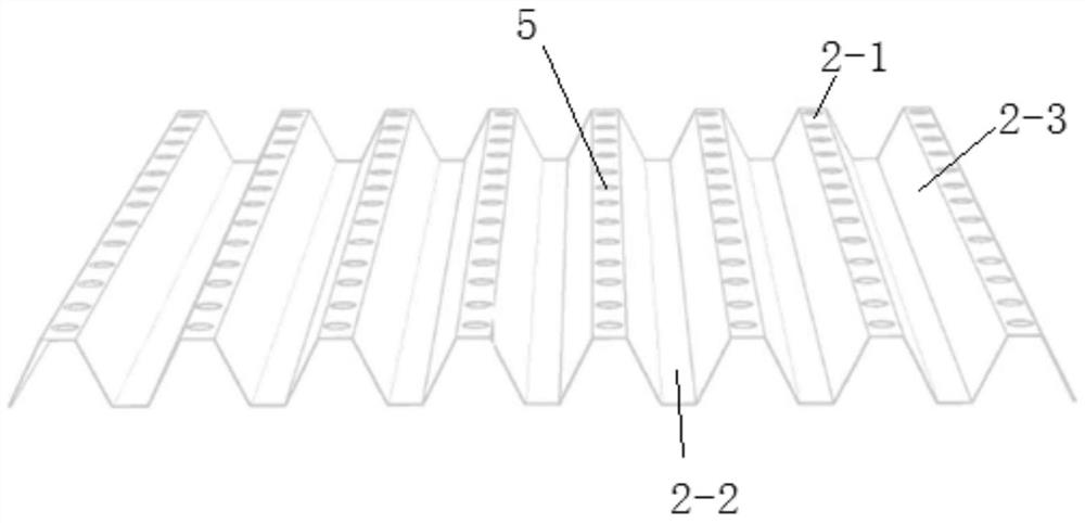
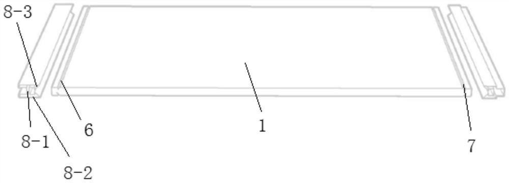
[0031] This embodiment provides a roadbed drainage device for embedding in the roadbed, such as Figure 1-Figure 3 As shown, it includes a drainage substrate 1, a wave plate 2 and a geotextile 3. The wave plate 2 is laid on the upper surface of the drainage substrate 1, and the geotextile 3 is laid on the top of the wave plate 2. The wave plate 2 has crests and troughs, and the wave plate 2 The part of the wave crest on the upper surface is attached to the geotextile 3, and the rest of the upper surface of the wave plate 2 is not attached to the geotextile 3, so that the upper surface of the wave plate 2 and the lower surface of the geotextile 3 form a ventilation space 4, which increases the geotextile. The contact area of ​​the cloth 3 with the air.

[0032] The drainage substrate 1 in this embodiment adopts a rectangular plate, and the wave plate 2 is fixed at the middle of the upper surface of the drainage substrate 1 .

[0033] In order to increase the fixing strength be...

Embodiment 2

[0060] This embodiment provides a subgrade structure, in which the subgrade drainage device described in Embodiment 1 is buried inside, and a plurality of subgrade drainage devices are arranged along the longitudinal direction of the subgrade structure, and the drainage substrate 1 of the adjacent subgrade drainage device passes through the plug 11 and the slot 10 are plugged and connected, the length direction of the ventilation space 4 formed by the geotextile 3 and the wave plate 2 is set along the width direction of the subgrade structure, and the end of the ventilation space 4 extends to the side of the subgrade structure so that the ventilation space 4 and The external space of the subgrade structure is connected.

[0061] The construction method of the subgrade structure of the present embodiment is:

[0062] According to the width of the cross-section of the subgrade structure, determine the length and quantity of the drainage substrate 1, determine the length and quan...


PUM


Abstract

The roadbed drainage device comprises a drainage base plate, a waved plate is laid on the upper surface of the drainage base plate, geotechnical cloth is laid on the waved plate, the geotechnical cloth is attached to the wave crest position of the upper surface of the waved plate, and a ventilation space is formed between other parts of the upper surface of the waved plate and the geotechnical cloth. The roadbed drainage device is good in drainage effect and good in roadbed humidity control effect.

Description

technical field [0001] The invention relates to the technical field of roadbed humidity control, in particular to a roadbed drainage device and a roadbed structure. Background technique [0002] The statements herein merely provide background information related to the present invention and do not necessarily constitute prior art. [0003] During the roadbed construction and open traffic service period, affected by groundwater, atmospheric precipitation, land water evaporation, pavement structure permeation and traffic load, the humidity of the roadbed is constantly changing, and the humidity during service often exceeds the optimal moisture content, resulting in wet roadbeds. The mechanical properties gradually decline, further leading to the frequent occurrence of road engineering diseases such as embankment subsidence and pavement cracking, and the reduction of road life. Good subgrade support and its long-term stability depend primarily on the control of the subgrade mo...

Claims


Application Information

Patent Timeline
Patent Type & Authority Applications(China)
IPC IPC(8): E01C3/06E01C3/04
CPCE01C3/06E01C3/04
Inventor 蒋红光迟浩然王凯姚占勇李景磊张宁栗剑姚凯梁明张吉哲
Owner SHANDONG UNIV
Learn More