
Switch type self-generating system

A self-generating, switch-type technology, applied in the field of switches, can solve problems such as accidents, electronic devices stop working, inconvenience, etc., and achieve the effect of reducing maintenance work and costs

Active Publication Date: 2022-04-22
弦科技有限公司
View PDF4 Cites 0 Cited by
  • Summary
  • Abstract
  • Description
  • Claims
  • Application Information

AI Technical Summary

Problems solved by technology

The use of electronic devices requires a corresponding power supply to operate. If the battery is used for power supply, when the battery is exhausted and the user forgets to replace it, the electronic device will stop working, which is very inconvenient
If the mains power supply is used, the risk of accidents caused by electric leakage is more likely to occur due to the relatively humid environment such as toilets or bathrooms

Method used


Image

  • Switch type self-generating system
  • Switch type self-generating system
  • Switch type self-generating system

Examples


Embodiment Construction

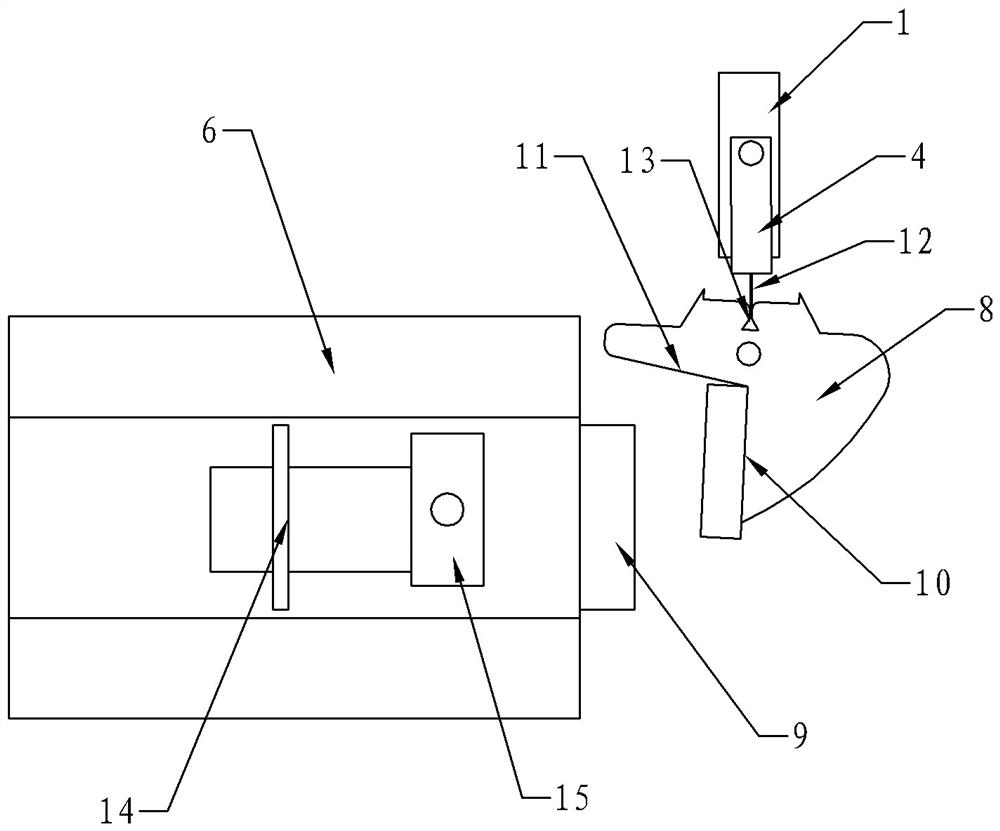
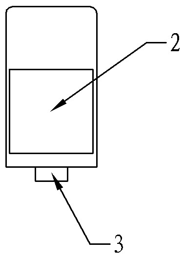
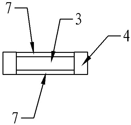
[0024] Such as figure 1 , a switch-type self-generating system, including a generating coil module 1, which is at least composed of a coil 2 and a magnetically permeable core 3 in the coil 2. Coil 2 generates electric current by the change of the magnetic flux in induction magnetic permeable core 3, for this reason the present invention is provided with movable support 4 at generating coil module 1, and magnetic body 5 is set on movable support 4, by making the different magnetic poles of magnetic body 5 and The magnetic permeable core 3 contacts to realize the change of magnetic flux. The specific structure of the movable support 4 is as follows: one end is provided with a rotating shaft, which is connected to the generator coil module 1 through the rotating shaft; the other end is a free end, which is connected to the switch device 6, and the free end can drive the movable support when the switch device 6 is active. 4 swing around the rotating shaft, the magnetic body 5 is ...


PUM


Abstract

The invention provides a switch type self-generating system which comprises a generating coil module at least composed of a coil and a magnetic conductive core in the coil. The coil generates current by inducting the change of magnetic flux in the magnetic conductive core, so that the movable support is arranged on the power generation coil module, the magnetic body is arranged on the movable support, different magnetic poles of the magnetic body are in contact with the magnetic conductive core, the change of the magnetic flux is realized, and the coil generates electric quantity by inducting the change of the magnetic flux to be used by an electric device. The whole system does not need to be powered by a battery or a mains supply, so that a circuit part can adopt a fully-sealed structure to prevent a humid environment in facilities such as a door lock of a toilet or a bathroom from influencing the service life of the circuit part, the system does not need to be maintained if no fault occurs, and the maintenance work and cost are greatly reduced.

Description

technical field [0001] The invention relates to a switch capable of realizing self-power generation. Background technique [0002] With the continuous development of smart homes this year, such as toilets, bathrooms, etc., it is also necessary to use some electronic devices to send some signals to the server or controlled equipment through the electronic devices, so that the server or controlled equipment can process or respond accordingly. The use of electronic devices requires a corresponding power supply to operate. For example, using a battery for power supply, when the battery is exhausted and the user forgets to replace it, the electronic device will stop working, which is very inconvenient. If the mains power supply is used, the risk of accidents caused by electric leakage is more likely to occur due to the relatively humid environment such as toilets or bathrooms. Especially for facilities such as toilet or bathroom door locks, it is hoped to know its working statu...

Claims


Application Information

Patent Timeline
Patent Type & Authority Applications(China)
IPC IPC(8): E05B17/00E05B3/00E05B15/10F03G5/00H02K35/02H02K7/18
CPCE05B17/00E05B3/00E05B15/10F03G5/00H02K35/02H02K7/1876
Inventor 吴志超
Owner 弦科技有限公司
Learn More