Supercharge Your Innovation With Domain-Expert AI Agents!

Piston sealing structure of hydraulic drive piston hydrogen compressor

A technology of sealing structure and compressor, which is applied in the direction of piston rings, liquid variable capacity machines, mechanical equipment, etc., can solve the problems of universal plug failure, achieve reliable structure, long service life, and prevent uneven changes in outer diameter

Pending Publication Date: 2022-04-22
XI AN JIAOTONG UNIV +1
View PDF3 Cites 0 Cited by
  • Summary
  • Abstract
  • Description
  • Claims
  • Application Information

AI Technical Summary

Problems solved by technology

[0005] The invention proposes a piston sealing structure of a liquid-driven piston hydrogen compressor to solve the problem that the existing pan-seal used for piston sealing fails when the design life is not reached

Method used


Image

  • Piston sealing structure of hydraulic drive piston hydrogen compressor
  • Piston sealing structure of hydraulic drive piston hydrogen compressor

Examples


Embodiment 1

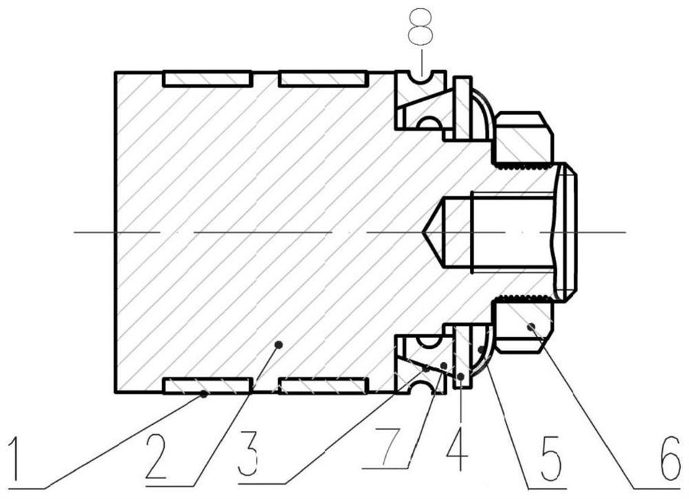
[0020] Embodiment 1: A piston seal structure of a liquid-driven piston hydrogen compressor, including two support rings 1 sleeved on the piston body 2, and sleeved on the end of the piston body 2 away from the piston rod.

[0021] The elastic sealing assembly includes a first ring 3 and a second ring 7, the first ring 3 is sleeved on the outer wall of the second ring 7, and the contact surface between the first ring 3 and the second ring 7 is a conical surface There is a gap between the end surface of the second ring member 7 away from the extrusion assembly and the end surface of the piston body 2 . When the elastic sealing assembly is squeezed, it will generate force to the piston body 2 and the cylinder respectively, so that the second ring 7 is in close contact with the piston body 2, while the first ring 3 is in close contact with the cylinder wall.

[0022] Grooves 8 are formed at the center of the first ring 3 close to the side wall of the cylinder, and at the center of...


PUM


Abstract

The invention relates to the technical field of hydraulic-drive piston hydrogen compressors, in particular to a piston sealing structure of a hydraulic-drive piston hydrogen compressor, which comprises a support ring, an elastic sealing assembly and an extrusion assembly, the extrusion assembly is used for applying pre-tightening force to the elastic sealing assembly, and a limiting space used for limiting axial movement of the elastic sealing assembly is formed between the piston body and the extrusion assembly; when the extrusion assembly applies pre-tightening force to the elastic sealing assembly, the elastic sealing assembly expands in the circumferential direction and makes close contact with the inner wall of the air cylinder. According to the piston sealing structure of the hydraulic drive piston hydrogen compressor, the problem that an existing spring plug used for piston sealing fails before the designed service life is reached is solved.

Description

technical field [0001] The invention relates to the technical field of a liquid-driven piston hydrogen compressor, in particular to a piston sealing structure of a liquid-driven piston hydrogen compressor. Background technique [0002] The liquid-driven piston hydrogen compressor is a reciprocating volumetric compressor. It is used in hydrogenation because it is better than the traditional crank-connecting rod reciprocating compressor in terms of sealing, stability, vibration, etc., and has a larger compression ratio. In petrochemical fields such as stations, various high-purity gases, flammable, explosive, toxic and harmful gases that should not be leaked are compressed and transported. In the liquid-driven piston compressor, the motor drives the hydraulic oil pump to alternately supply the hydraulic oil to both ends of the cylinder piston to push the cylinder piston to make a reciprocating linear motion. The cylinder piston drives the piston rod to push the cylinder pisto...

Claims


Application Information

Patent Timeline
IPC IPC(8): F16J9/06F04B39/00
CPCF16J9/066F04B39/0005
Inventor 贾晓晗计泽灏李佐良彭学院
Owner XI AN JIAOTONG UNIV
Features
  • R&D
  • Intellectual Property
  • Life Sciences
  • Materials
  • Tech Scout
  • Unparalleled Data Quality
  • Higher Quality Content
  • 60% Fewer Hallucinations
Learn More