Method and device for fixing thermocouple in steel-plate-encased concrete composite member

A technology of composite components and outsourcing steel plates, which is applied in the direction of using electrical devices, measuring devices, and thermometers using electric/magnetic elements that are directly sensitive to heat, can solve the problem that the accuracy of the measuring point position cannot be guaranteed and the occurrence of thermocouple disturbances Offset, thermocouples are vulnerable to impact, etc., to achieve the effect of optimizing the construction sequence, ensuring accurate positioning, and easy operation

Active Publication Date: 2022-04-22
SOUTH CHINA UNIV OF TECH
View PDF7 Cites 0 Cited by
  • Summary
  • Abstract
  • Description
  • Claims
  • Application Information

AI Technical Summary

Problems solved by technology

However, the existing methods of fixing thermocouples have the following disadvantages: ①The welding temperature is too high, which will cause damage to the thermocouple itself, resulting in a decrease in measurement accuracy; Accuracy cannot be guaranteed; ③ Thermocouples are vulnerable to impact and damage during concrete pouring

Method used


Image

  • Method and device for fixing thermocouple in steel-plate-encased concrete composite member
  • Method and device for fixing thermocouple in steel-plate-encased concrete composite member
  • Method and device for fixing thermocouple in steel-plate-encased concrete composite member

Examples


Embodiment 1

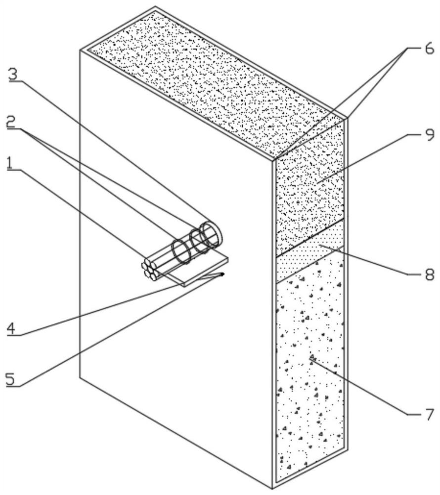
[0052] The cross-section of the vertical composite member used in this embodiment is rectangular, and the drilling position and the drilling of the outer cladding steel plate of the experimental member are determined according to the temperature field measurement position, and the position and quantity of the thermocouple measuring points along the thickness direction are determined according to the measurement needs;

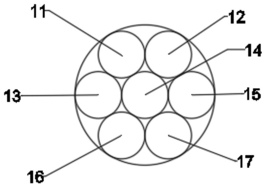
[0053] Arrange the thermocouples and bind them into a thermocouple bundle. The cross section of the thermocouple bundle is as follows: Figure 3a As shown, measure the distance from the measuring point to the outer surface of the drilled steel plate on the thermocouple and mark it;

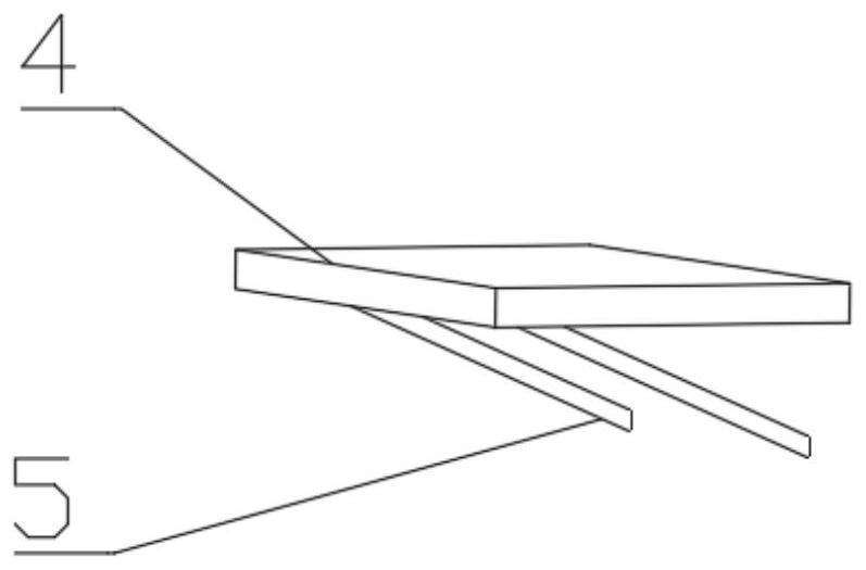
[0054] Weld the fixing bracket on the outer surface of the experimental component;

[0055] First pour the concrete under the drilled hole and vibrate it compactly, and make the upper surface of the concrete flush with the lowest point of the drilled hole;

[0056] Extend the ther...

Embodiment 2

[0059] The cross-section of the vertical composite member used in this embodiment is circular, and the drilling position and number of the outer cladding steel plate of the experimental member are determined and drilled according to the temperature field measurement position, and the position and quantity of the thermocouple measuring points along the thickness direction are determined according to the measurement needs;

[0060] Arrange the thermocouples and bind them into a thermocouple bundle. The cross section of the thermocouple bundle is as follows: Figure 5 As shown, mark the position of the outer surface of the experimental component corresponding to the drilled hole on the thermocouple bundle;

[0061] Weld the fixing bracket on the outer surface of the experimental component;

[0062] First pour the concrete under the drilled hole and vibrate it compactly, and make the upper surface of the concrete flush with the lowest point of the drilled hole;

[0063] Extend th...

Embodiment 3

[0066] The cross-section of the vertical composite member used in this embodiment is I-shaped, and the drilling position of the outer steel plate of the experimental member is determined and drilled according to the temperature field measurement position, and the position and number of thermocouple measuring points along the thickness direction are determined according to the measurement needs;

[0067] Arrange the thermocouples and bind them into a thermocouple bundle. The cross section of the thermocouple bundle is as follows: Image 6 As shown, measure the distance from the measuring point to the outer surface of the drilled steel plate on the thermocouple and mark it;

[0068] Weld the fixing bracket on the outer surface of the experimental component;

[0069] First pour the concrete under the drilled hole and vibrate it compactly, and make the upper surface of the concrete flush with the lowest point of the drilled hole;

[0070] Extend the thermocouple bundle from the d...


PUM


Abstract

The invention relates to a method and a device for fixing thermocouples in a steel-plate-wrapped concrete combined member. The method comprises the following steps: determining the position and the diameter of a drilling hole of a steel plate wrapped by the member according to the measurement position of a temperature field and the number of the thermocouples; measuring the distance from a measuring point to the outer surface of the drilling steel plate on the thermocouples, marking the distance, arranging the thermocouples in an approximately circular shape, and binding the thermocouples at a non-extending section by using an iron wire; a through round hole is drilled in the position of the steel plate of the component, and the fixing support is welded to the component; firstly, concrete is poured to the lowest point of a round hole, a thermocouple extends from the round hole to the marked position and is fixed to a support, and the concrete is poured manually and covers the thermocouple; and finally, upper concrete is poured and vibrated compactly. By using the method, the thermocouple in the combined member can be accurately positioned and fixed, so that the internal concrete temperature field can be measured, the damage to the member and the thermocouple is small, the method is simple, and the operation is easy.

Description

technical field [0001] The invention relates to the technical field of building disaster prevention and mitigation, in particular to a method and device for fixing an internal thermocouple of an outsourcing steel plate concrete composite member. Background technique [0002] Outer steel plate concrete composite structure is a combined structure in which the outer steel plate and the inner filling concrete form a joint working system through connectors such as studs. Common vertical composite members in actual engineering include steel plate rectangular concrete columns, circular steel tube concrete columns, outsourcing steel plate concrete special-shaped columns, and outsourcing steel plate concrete composite shear walls, etc. In terms of mechanical properties, this composite structure combines the good compressive performance of concrete and the superior tensile performance of steel plates. It has high bearing capacity and has superior earthquake resistance and good impact ...

Claims


Application Information

Patent Timeline
IPC IPC(8): G01K7/02G01K1/14
CPCG01K7/02G01K1/14
Inventor 韦锋杨钧鸿苏成
Owner SOUTH CHINA UNIV OF TECH
Why Eureka
Try Eureka