Filling body for airtight test

An airtight test and filling body technology, which is applied in the application of light to test the fluid tightness, detect the appearance of fluid at the leakage point, and use liquid/vacuum to measure the liquid tightness, etc. It can solve the problems of poor versatility of the filling body. , to achieve the effect of improving service life, improving versatility, and ensuring pressure bearing capacity

Pending Publication Date: 2022-04-22
PINGGAO GRP +1
View PDF1 Cites 0 Cited by
  • Summary
  • Abstract
  • Description
  • Claims
  • Application Information

AI Technical Summary

Problems solved by technology

[0005] The purpose of the present invention is to provide a filling body for airtight test to solve the technical problem of poor versatility of the filling body due to the integrated design of the filling body in the prior art

Method used


Image

  • Filling body for airtight test
  • Filling body for airtight test
  • Filling body for airtight test

Examples


Embodiment 1

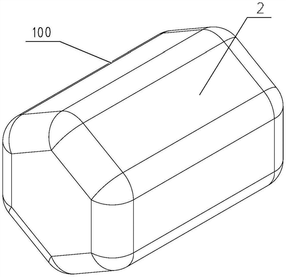
[0048] The filling body 100 used in the gas sealing test in the prior art is a large-scale tooling designed in one piece, and its shape is only suitable for testing tanks of corresponding shapes. If it is necessary to perform leak detection on other shells, it needs to be redesigned. The filling body 100 adapted to the casing, especially when the factory manufactures casings of various shapes, it is necessary to design and manufacture a large number of filling bodies 100 adapted to the corresponding casings, and the cost is relatively high. However, the filling body 100 for the airtight test provided by the present invention is designed in a separate and miniaturized form, and each filling body 100 can be magnetically attracted together. The filler of the airtight cavity 110 can fully occupy the inner space of the airtight cavity 110 , and then inject a small amount of gas into the airtight cavity 110 , which saves costs and improves the versatility of the filler 100 .

[0049...

specific Embodiment 2

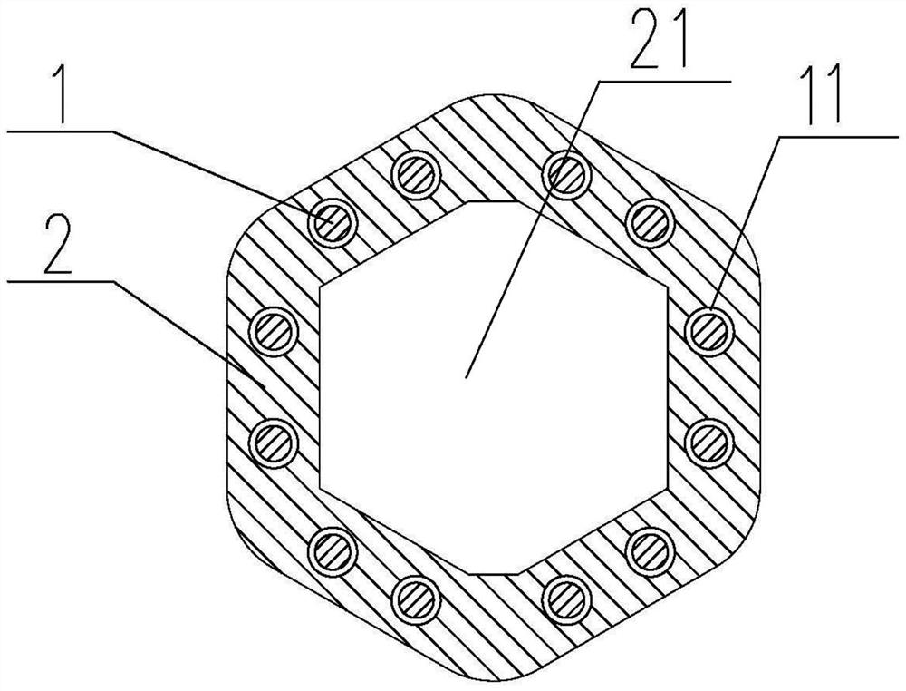
[0058] The main difference between it and Embodiment 1 is that in Embodiment 1, the weight reducing cavity 21 is hollow. In this embodiment, when the strength of the material forming the pressure-resistant casing 2 is not high enough, such as Figure 4 As shown, the lightweight filler 3 needs to be filled in the weight-reducing cavity 21. Specifically, the lightweight filler can be ceramsite, mineral wool, asbestos, polyester foam, etc., and the lightweight filler 3 is filled with the pressure-resistant shell 2. The cavity 21 is heavy to increase the overall strength of the filling body 100 .

specific Embodiment 3

[0060] The main difference between it and the embodiment 2 is that in the embodiment 2, the light weight filler 3 is filled in the weight reduction cavity 21 to increase the strength of the filler body 100 . In this example, if Figure 5 As shown, a supporting frame 4 is provided in the weight-reducing cavity 21 of the pressure-resistant housing 2 , and the supporting frame 4 is supported and connected with the pressure-resistant housing 2 in the weight-reducing cavity 21 to increase the overall strength of the filling body 100 .

[0061] In actual implementation, the pressure-resistant shell 2 can be arranged in half. At this time, the weight-reducing cavity 21 is also set in half in the two-and-a-half pressure-resistant shell 2, and the support frame 4 is first filled into the two-and-a-half pressure-resistant shell. 2 in the weight-reducing cavity 21 of one of them, and then the two and a half pressure-resistant shells 2 are fastened and spliced ​​together, so that the supp...


PUM


Abstract

The invention relates to a filling body for an airtight test, which comprises a pressure-resistant shell used for bearing set gas pressure when the filling body is filled into a to-be-tested airtight cavity to carry out the airtight test, a plurality of rotation stopping planes are arranged on the pressure-resistant shell, each rotation stopping plane is provided with a rotating cavity, a magnetic bead is rotationally assembled in each rotating cavity, and the magnetic beads are arranged on the pressure-resistant shell. When a plurality of filling bodies are filled into a to-be-tested airtight cavity, the adjacent filling bodies are matched in a rotation stopping manner so as to prevent the filling bodies from rolling. When in use, a plurality of filling bodies are filled in the airtight cavity to be tested to serve as fillers of the airtight cavity to replace an integrated filling tool filled in the airtight cavity to be tested, so that the filling bodies can be suitable for various airtight cavities, the universality of the filling bodies is improved, the rotation stopping plane is arranged on the pressure-resistant shell, and the pressure-resistant shell is not prone to deformation. The filling bodies filled in the airtight cavity to be tested are prevented from being not easy to roll, and the plurality of filling bodies can be conveniently stacked and filled in the airtight cavity to be tested.

Description

technical field [0001] The invention relates to a filling body for an airtight test. Background technique [0002] According to the relevant standards of the high-voltage electrical appliance industry, the shells of high-voltage electrical appliances must pass the gas sealing test before leaving the factory to verify the quality of the products. At present, the more common gas sealing test methods are generally divided into three types, namely, vacuum leak detection, leak detection with leak detector, and infrared imaging leak detection. For vacuum leak detection, the air inside the shell needs to be evacuated. Whether the shell continues to maintain a vacuum state; for leak detection of leak detectors, it is necessary to fill the inside of the shell with tracer gas, so that the internal pressure of the shell reaches a certain level, to see if there is tracer gas leaking; for infrared imaging leak detection Generally speaking, it is necessary to fill the casing with sulfur ...

Claims


Application Information

Patent Timeline
Patent Type & Authority Applications(China)
IPC IPC(8): G01M3/04G01M3/38
CPCG01M3/04G01M3/38
Inventor 魏建巍林麟贺永明王向克陆静陈国营王刚刘龙白玮陈会龙贾彩玲王汉瑶李俊锋孙清超
Owner PINGGAO GRP
Why Eureka
Try Eureka