Double-span type dynamic pressure sliding bearing experiment table capable of applying dynamic load
A technology of sliding bearings and dynamic loads, which is applied in the direction of mechanical bearing testing, etc., can solve problems such as inability to guarantee loading stability, inability to test bearing characteristics, and inability to satisfy research, so as to achieve rapid load response, ensure data accuracy, and avoid tedious procedures Effect
- Summary
- Abstract
- Description
- Claims
- Application Information
AI Technical Summary
Problems solved by technology
Method used
Image
Examples
Embodiment 1
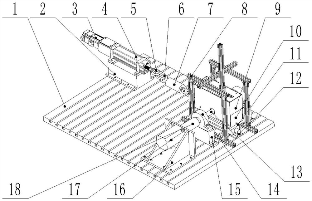
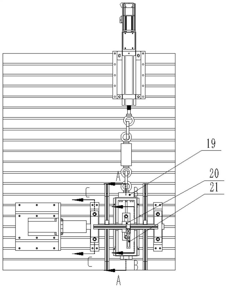
[0071] Study the influence of the misalignment of the main shaft 13 on the dynamic pressure sliding bearing 20:
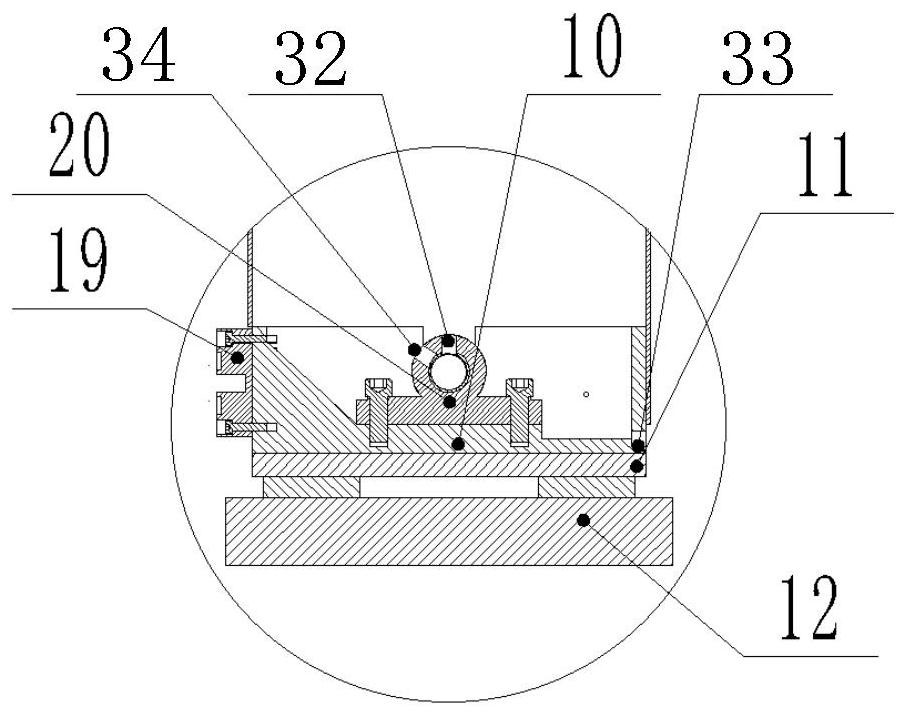
[0072] Such as Figure 1 to Figure 5 As shown, the middle part of the right side of platform 1 fixes the slide rail 12 with two sliders with T-slot special nut 29; Connect with the pad iron-10 of the sliding bearing seat through the inner hexagon bolt; install the dynamic pressure sliding bearing 20 through the inner hexagon bolt in the sliding bearing seat pad iron-10 as the experimental bearing, and the upper part of the dynamic pressure sliding bearing 20 has a hole for connecting the hydraulic pump The oil injection end provides lubricating oil for the dynamic pressure sliding bearing 20, and the lubricating oil flowing out from the dynamic pressure sliding bearing 20 flows into the inside of the sliding bearing seat pad iron-10, and is recovered through the oil outlet hole 33 at the front end of the sliding bearing seat pad iron-10.
[0073] The aluminum prof...
Embodiment 2
[0080] To study the influence of the unbalance applied on the main shaft 13 on the sliding bearing rotor system formed by the coupling of the dynamic pressure sliding bearing 20 and the main shaft 13:
[0081] Such as Figure 6 As shown, on the basis of the structure of the experimental bench in Embodiment 1, disconnect the bolt connection between the spoke pressure sensor 19 and the pad iron 10 of the sliding bearing seat, remove the supporting bearing system away from the servo motor 17, and place the experimental bearing system Move to a position far away from the servo motor 1 17, and remove the sliding bearing pad iron 2 11, slider and slide rail 12, and install the experimental bearing system on the sliding bearing pad 3 22 through bolts, and the sliding bearing pad 3 22 It is installed on the platform 1 through a T-slot special nut 29 . Installing the experimental bearing system to the position of the supporting bearing is closer to the working condition of the dynamic...
Embodiment 3
[0084] To study the influence of dynamic load applied to the rolling bearing on the sliding bearing rotor system formed by the coupling of the dynamic pressure sliding bearing 20 and the main shaft 13:
[0085] Such as Figure 7 As shown, on the basis of the structure of the experimental bench in Embodiment 1, the bolted connection between the spoke pressure sensor 19 and the pad iron of the sliding bearing seat 10 is disconnected, and the supporting bearing system far away from the servo motor 17 is exchanged with the experimental bearing system Position; the experimental bearing system removes the sliding bearing pad iron 2 11, the slider and the slide rail 12, and the experimental bearing system is installed on the platform 1 through the sliding bearing pad 3 22 and the special T-slot nut 29; away from the servo motor 1 17 The supporting bearing system removes the rolling bearing seat pad iron one 15, and then connects it to the slider of the slide rail 12 through the rolli...
PUM
 Abstract
Description
Claims
Application Information
 - R&D
- Intellectual Property
- Life Sciences
- Materials
- Tech Scout
- Unparalleled Data Quality
- Higher Quality Content
- 60% Fewer Hallucinations
Browse by: Latest US Patents, China's latest patents, Technical Efficacy Thesaurus, Application Domain, Technology Topic, Popular Technical Reports.
© 2025 PatSnap. All rights reserved.Legal|Privacy policy|Modern Slavery Act Transparency Statement|Sitemap|About US| Contact US: help@patsnap.com


