System and method for measuring emission angle of optical antenna

An optical antenna and measurement system technology, applied in radio wave measurement systems, measurement devices, measurement angles and other directions, can solve problems such as the influence of the optical system, the poor accuracy of releasing the ball, and the difficulty of calibration, achieve simple and accurate calculation, improve measurement accuracy, Easy-to-use effects

Pending Publication Date: 2022-04-22
CHENGDU KAITIAN ELECTRONICS
View PDF0 Cites 0 Cited by
  • Summary
  • Abstract
  • Description
  • Claims
  • Application Information

AI Technical Summary

Problems solved by technology

Traditional methods have many limitations in use. For example, the method of using celestial constellations to calibrate the optical antenna must be carried out on a clear night with high visibility; the method of releasing the balloon has poor accuracy.
In the absence of an effective reference object, it is very difficult to correct the direction of the optical antenna, and the direction can only be guaranteed by the precision of the structural processing of the optical antenna. and supporting structures will be deformed at different levels, and these deformations will have unpredictable effects on the optical system

Method used


Image

  • System and method for measuring emission angle of optical antenna
  • System and method for measuring emission angle of optical antenna
  • System and method for measuring emission angle of optical antenna

Examples


Embodiment 1

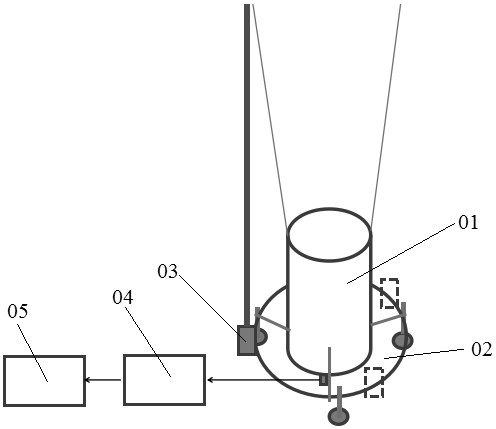
[0042] A measurement system for the emission angle of an optical antenna, such as figure 1 As shown, it includes a laser emitting device 03, a photoelectric conversion device 04, a data acquisition and processing device 05, a horizontal inclinometer 45 and an equipment support 02; the receiving end of the optical antenna 01 is connected with the photoelectric conversion device 04 and the data acquisition and processing device 05 in sequence; The outer side of the optical antenna 01 is equipped with an equipment bracket 02, and the optical antenna 01 and the equipment bracket 02 are arranged on a concentric axis; a horizontal inclinometer 45 and several laser emitting devices 03 are arranged on the circumference of the equipment bracket 02; the photoelectric conversion The device 04 is used to collect the echo signal of the optical antenna 01 and convert it into an electrical signal, and the data collection and processing device 05 is used to collect the electrical signal and co...

Embodiment 2

[0047] This embodiment is optimized on the basis of embodiment 1, such as Figure 6 As shown, the equipment support 02 includes an annular main support 41, a coaxial support 43, a horizontal support frame 42 and a laser emitting hanger 44, and several coaxial supports 43, laser emitting Hanger 44, horizontal support frame 42; the ring-shaped main bracket 41 is sleeved on the outside of the optical antenna 01, and the ring-shaped main bracket 41 and the optical antenna 01 are concentrically arranged, and the coaxial bracket 43 passes through the ring-shaped main bracket 41 transversely And contact with the optical antenna 01 ; the laser emitting device 03 is arranged on the laser emitting hanger 44 , and the horizontal inclinometer 45 is arranged on the annular main support 41 .

[0048] Further, several coaxial brackets 43 , laser emitting hangers 44 , and horizontal support brackets 42 are equidistantly arranged in the circumferential direction of the annular main bracket 41 ...

Embodiment 3

[0052] This embodiment is optimized on the basis of embodiment 2, such as Figure 7 As shown, the coaxial bracket 43 includes a T-shaped bracket 431, a bracket main body 432, a bracket fine-tuning device 433 and a locking buckle 434. The fine-tuning device 433 is connected with the ring-shaped main bracket 41, and the bracket main body 432 is provided with several grooves along the length direction, and the locking buckle 434 passes through the bracket fine-tuning device 433 and locks with the grooves; the bracket main body 432 A T-shaped bracket 431 is provided at the abutting end of the bracket body 432 , and scale lines are provided along the length direction of the bracket main body 432 .

[0053] Further, the outer end of the bracket main body 432 is provided with a bracket auxiliary scale 435 feet.

[0054] Further, the bracket fine-tuning device 433 is rotationally connected with the ring-shaped main bracket 41 , and the bracket main body 432 is slidably connected with...


PUM


Abstract

The invention discloses a measurement system and a measurement method for an emission angle of an optical antenna. The measurement system comprises a laser emission device, a photoelectric conversion device, a data acquisition and processing device, a horizontal inclinometer and an equipment bracket, the receiving end of the optical antenna is sequentially connected with a photoelectric conversion device and a data acquisition and processing device; the outer side of the optical antenna is sleeved with an equipment support, and the optical antenna and the equipment support are coaxially arranged. A horizontal inclinometer and a plurality of laser emitting devices are arranged in the circumferential direction of the equipment bracket; the photoelectric conversion device is used for collecting echo signals of the optical antenna and converting the echo signals into electric signals, and the data collecting and processing device is used for collecting the electric signals and converting the electric signals into distance information so as to determine the emission angle of the optical antenna. The device is used for calibrating and detecting the transmitting direction of the optical antenna, daily maintenance and performance testing of the optical antenna can be met, an experiment can be carried out on any optical antenna, and the measurement precision is effectively improved.

Description

technical field [0001] The invention belongs to the technical field of optical antenna calibration equipment, and in particular relates to a measurement system and a measurement method for an optical antenna emission angle. Background technique [0002] The calibration of the transmitting and receiving direction of the traditional optical antenna mainly depends on the reference object at a fixed position. Typical celestial body constellations can be used to calibrate the optical antenna, such as ballooning. Traditional methods have many limitations in use. For example, the method of using celestial constellations to calibrate the optical antenna must be carried out on a clear night with high visibility; the method of releasing the balloon has poor accuracy. In the absence of an effective reference object, it is very difficult to correct the direction of the optical antenna, and the direction can only be guaranteed by the precision of the structural processing of the optical ...

Claims


Application Information

Patent Timeline
Patent Type & Authority Applications(China)
IPC IPC(8): G01S7/497G01C1/00
CPCG01S7/497G01C1/00
Inventor 刘兴涛薛磊龙彦志吴梅陈浩张亚筠张果
Owner CHENGDU KAITIAN ELECTRONICS
Why Eureka
Try Eureka