
Clinical brain operation auxiliary equipment for neurosurgery department

A neurosurgery and auxiliary equipment technology, applied in the directions of surgery, operating table, stereotaxic surgical instruments, etc., can solve the problems of inconvenient use, inconvenient cleaning of the head pad, single function of the fixing device, etc., to achieve convenient disassembly and installation, and prevent breeding. Bacteria, the effect of facilitating surgical work

Inactive Publication Date: 2022-04-26
焦作煤业(集团)有限责任公司中央医院
View PDF0 Cites 1 Cited by
  • Summary
  • Abstract
  • Description
  • Claims
  • Application Information

AI Technical Summary

Problems solved by technology

[0002] Neurosurgery is a branch of surgery, which uses unique neurosurgery research methods to study the human nervous system, such as the brain, spinal cord and peripheral nervous system, as well as related diseases, based on surgery as the main treatment method. Subsidiary organs, such as skull, scalp, cerebrovascular meninges and other structural injuries, inflammation, tumors, deformities, and certain genetic metabolic disorders or dysfunctional diseases; The head of the patient is fixed, but the function of the existing fixing device is relatively single. It is inconvenient to clean the head pad, and it is not convenient for the next use. Therefore, it is necessary to design a neurosurgery clinical brain surgery auxiliary device

Method used


Image

  • Clinical brain operation auxiliary equipment for neurosurgery department
  • Clinical brain operation auxiliary equipment for neurosurgery department
  • Clinical brain operation auxiliary equipment for neurosurgery department

Examples


Embodiment 1

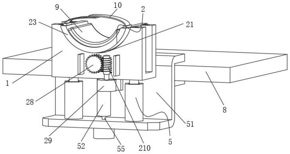
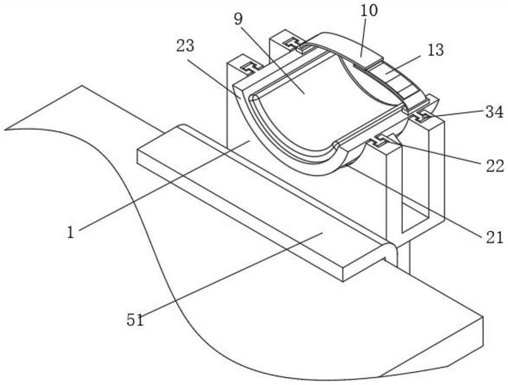
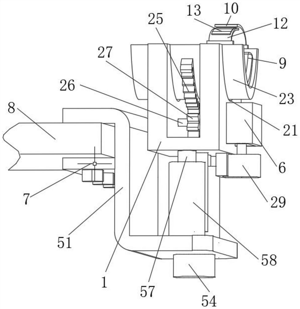
[0026] like Figure 1-6 As shown, a neurosurgery clinical brain operation auxiliary equipment includes a U-shaped board 1, a rotating assembly 2, a fixed assembly 3 and a lifting assembly 5, the top outer wall of the U-shaped board 1 is provided with a rotating assembly 2, and the outer wall of the A fixed assembly 3 is provided, and a lifting assembly 5 is provided on the outer wall of the bottom end of the U-shaped plate 1; a protective cover 6 is installed on one side of the U-shaped plate 1 corresponding to the worm gear 28, which plays a protective role. 28 and worm 210 are pinched;

[0027] The rotating assembly 2 includes an arc groove 21, a T-shaped chute 22, an arc-shaped plate 23, a T-shaped slider 24, an arc-shaped tooth plate 25, a first rotating shaft 26, a first gear 27, a worm wheel 28, and a first rotating motor 29 And worm screw 210, on the top outer wall of U-shaped plate 1 two vertical plates, be provided with arc groove 21, be provided with T-shaped chute ...

Embodiment 2

[0030] like figure 2 , 4 As shown in and 5, the fixed assembly 3 includes a first insertion slot 31, a first insertion block 32, a mounting slot 33, a first through hole 34, a second through hole 35, a U-shaped lever 36, a spring 37 and a slot 38. The outer wall of the arc plate 23 located on one side of the arc tooth plate 25 is provided with a first insertion groove 31, and a first insertion block 32 is inserted in the inside of the first insertion groove 31, and the first insertion block The inside of 32 is provided with a mounting groove 33, and a first through hole 34 is formed on the inner wall of one side of the mounting groove 33, and a second through hole 35 is formed on the inner wall of the mounting groove 33 on one side of the first through hole 34. The inside of the mounting groove 33 is slidably mounted with a U-shaped clamping rod 36 corresponding to the first through hole 34 and the second through hole 35, and the two ends of the U-shaped clamping rod 36 pass...

Embodiment 3

[0033] like Figure 1-3 As shown, the lifting assembly 5 includes a Z-shaped bottom plate 51, a first sleeve 52, a moving block 53, a second rotating motor 54, a screw mandrel 55, a second stopper 56, a guide rod 57 and a conduit 58, and the U-shaped plate 1 A first sleeve 52 is welded on the bottom outer wall, and a Z-shaped bottom plate 51 is installed below the first sleeve 52. A second rotating motor 54 is installed on the bottom outer wall of the Z-shaped bottom plate 51, and the output shaft of the second rotating motor 54 is Corresponding first sleeve pipe 52 is connected with screw mandrel 55 on the top end, and the top end of screw mandrel 55 is positioned at the first sleeve pipe 52, and the corresponding screw mandrel 55 is fixed with moving block 53 on the bottom inner wall of first sleeve pipe 52, and moves Block 53 is threadedly connected with screw mandrel 55, and Z-shaped bottom plate 51 is positioned at screw mandrel 55 both sides and all is welded with condui...


PUM


Abstract

The invention discloses neurosurgery clinical brain surgery auxiliary equipment which comprises a U-shaped plate, a rotating assembly, a fixing assembly and a lifting assembly, the rotating assembly is arranged on the outer wall of the top end of the U-shaped plate, the fixing assembly is arranged on the outer wall of the top end of the U-shaped plate, and the lifting assembly is arranged on the outer wall of the bottom end of the U-shaped plate; the rotating assembly comprises arc-shaped grooves, T-shaped sliding grooves, arc-shaped plates, T-shaped sliding blocks, arc-shaped toothed plates, a first rotating shaft, a first gear, a worm gear, a first rotating motor and a worm, the arc-shaped grooves are formed in the outer walls of the top ends of two vertical plates of the U-shaped plate, the T-shaped sliding grooves are formed in the inner walls of the bottom ends of the arc-shaped grooves, and the arc-shaped plates are installed on the inner walls of the arc-shaped grooves; the rotating assembly facilitates left-right fine adjustment, comparative use and improvement of the head of a patient, the lifting assembly facilitates height adjustment of a headrest on the arc-shaped plate, and therefore the height of the head of the patient is adjusted, operation work of medical staff is facilitated, and the device is worthy of wide application and popularization.

Description

technical field [0001] The invention relates to the technical field of neurosurgery equipment, in particular to a neurosurgery clinical brain operation auxiliary equipment. Background technique [0002] Neurosurgery is a branch of surgery, which uses unique neurosurgery research methods to study the human nervous system, such as the brain, spinal cord and peripheral nervous system, as well as related diseases, based on surgery as the main treatment method. Subsidiary organs, such as skull, scalp, cerebrovascular meninges and other structural injuries, inflammation, tumors, deformities, and certain genetic metabolic disorders or dysfunctional diseases; The head of the patient is fixed, but the function of the existing fixing device is relatively single. It is inconvenient to clean the head pad, and it is inconvenient to use next time. Therefore, it is necessary to design a neurosurgery clinical brain operation auxiliary device. Contents of the invention [0003] The purpo...

Claims


Application Information

Patent Timeline
Patent Type & Authority Applications(China)
IPC IPC(8): A61B90/14A61G13/12
CPCA61B90/14A61G13/121A61G13/128
Inventor 陈竹
Owner 焦作煤业(集团)有限责任公司中央医院
Learn More