
Rotor valve core of hydraulic 1D digital rotary valve

A rotor valve, digital technology, applied in the direction of fluid pressure actuators, servo motor components, mechanical equipment, etc., can solve the problems of reducing valve control accuracy and response speed, affecting assembly accuracy, increasing assembly difficulty, etc., to improve control accuracy and response speed, reduced size and weight, and no transmission power loss

Pending Publication Date: 2022-04-26
海明(鞍山)精密液压技术有限公司
View PDF6 Cites 3 Cited by
  • Summary
  • Abstract
  • Description
  • Claims
  • Application Information

AI Technical Summary

Problems solved by technology

The above two one-dimensional spools are generally connected to the rotary valve spool through the motor output shaft, which increases the difficulty of assembly and affects the assembly accuracy, and will reduce the control accuracy and response speed of the valve.
[0003] The two-dimensional (two degrees of freedom) hydraulic rotary valve drive mode is realized by the use of motor + mechanical converter. The mechanical converter has structures such as gear transmission, worm gear, screw nut, ball screw, cam, crank and crankshaft, etc. Due to the conversion error in mechanical conversion, at the same time, with the prolongation of the use time of these structures, the transmission parts continue to wear, the gap increases, and the conversion error is further increased, resulting in a decrease in control accuracy
The disadvantage is that the cumulative error of the transmission of the five-stage connection is very large, and the function of the valve is mainly the reversing effect, and the flow adjustment cannot be performed.
[0005] It can be seen that in the prior art, the spool of the one-dimensional or two-dimensional digital rotary valve is a separate structure from the motor, and its disadvantages are that it increases the difficulty of assembly, affects the assembly accuracy, and also reduces the control accuracy and accuracy of the rotary valve. The response speed cannot meet the requirements of digital rotary valves for switching accuracy and response speed

Method used


Image

  • Rotor valve core of hydraulic 1D digital rotary valve
  • Rotor valve core of hydraulic 1D digital rotary valve
  • Rotor valve core of hydraulic 1D digital rotary valve

Examples


Embodiment Construction

[0029] The technical solutions of the present invention will be clearly and completely described below in conjunction with the accompanying drawings. Apparently, the described embodiments are some of the embodiments of the present invention, but not all of them.

[0030] In order to more clearly illustrate the specific implementation of the present invention or the technical solutions in the prior art, the following will briefly introduce the accompanying drawings that need to be used in the specific implementation or description of the prior art. Obviously, the accompanying drawings in the following description The drawings show some implementations of the present invention, and those skilled in the art can obtain other drawings based on these drawings without any creative work.

[0031]The components of the embodiments of the invention generally described and shown in the figures herein may be arranged and designed in a variety of different configurations. Accordingly, the f...


PUM


Abstract

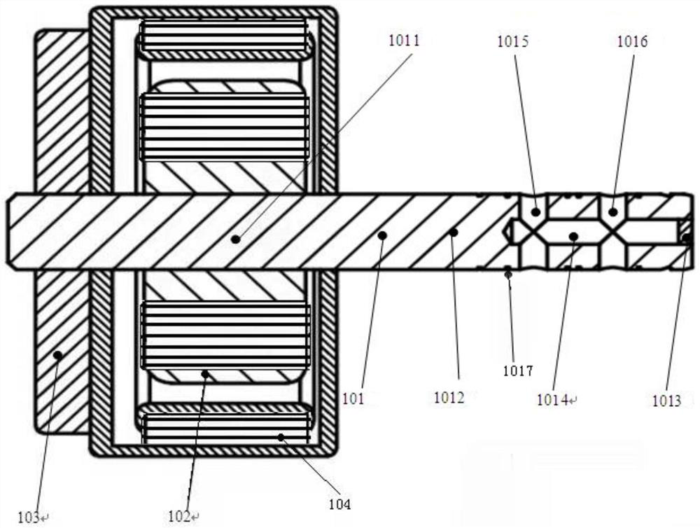
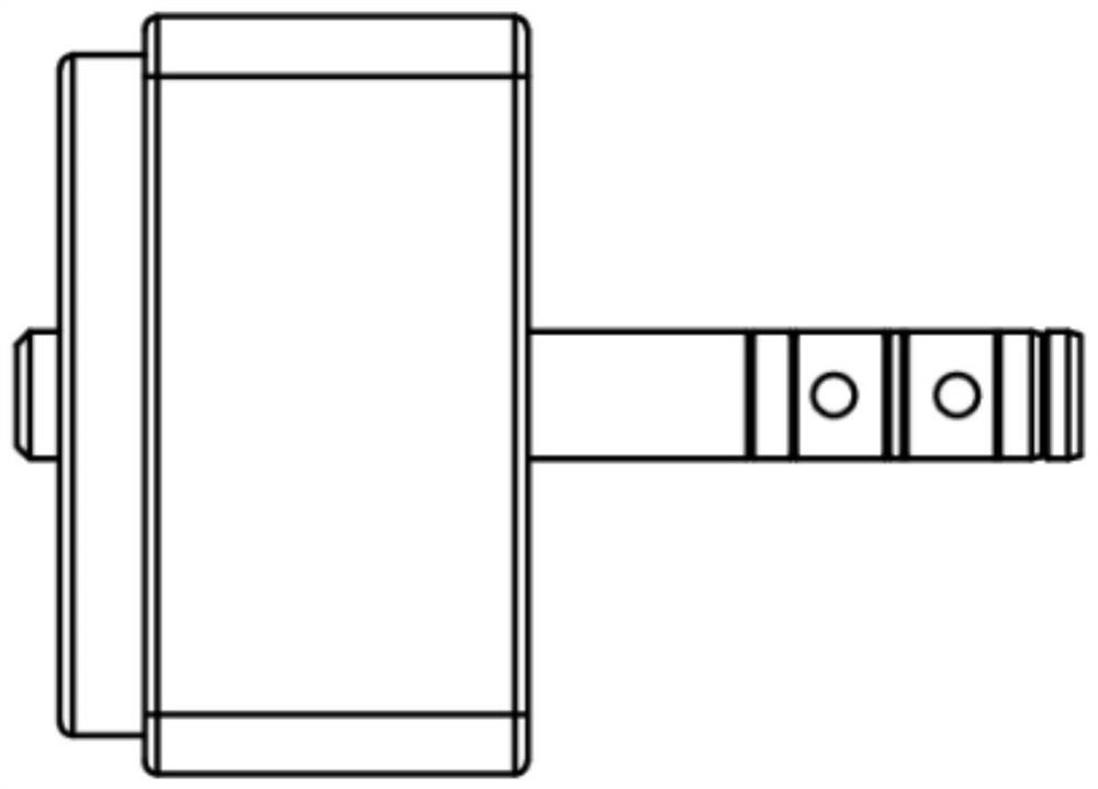
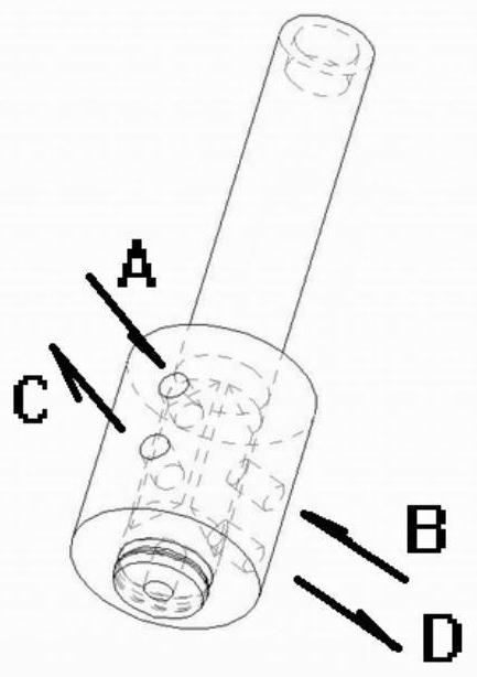
The invention relates to the technical field of fluid transmission and control digitization, in particular to a rotor valve core of a hydraulic 1D digital rotary valve, which is characterized by comprising a mandrel, a motor stator and an angular displacement sensor, one part of the core shaft is a motor rotor shaft, the other part of the core shaft is provided with a valve hole, the surface of the core shaft at the valve hole is provided with a plurality of grooves, the motor rotor shaft is coaxially matched with the motor stator, and the valve hole is matched with the valve sleeve; after the valve hole is matched with the valve sleeve, any logic control valve circuit of a two-position two-way valve core, a two-position three-way valve core, a two-position four-way valve core or a three-position four-way valve core is formed; the mandrel and the motor stator can form any one structure of a servo motor, a servo stepping motor or a rotary electromagnet, and digital control is achieved under the action of a control system. Compared with the prior art, the driving motor rotor and the rotor valve element are of an integrated structure, the structure is compact, the size and the weight are reduced, the assembly process is simplified, and the control precision and the response speed are improved.

Description

technical field [0001] The invention relates to the technical field of fluid transmission and control digitization, in particular to a rotor valve core of a hydraulic 1D digital rotary valve. Background technique [0002] Hydraulic valve products are widely used in fluid control in various technical fields. Currently, the visible hydraulic rotary valve spools are one-dimensional and two-dimensional. The Chinese invention patent with the application number 201310079796.X discloses a direct-feed digital hydraulic valve, including a command motor, a spline pair, a valve body, a spool, a feedback thread pair, and a feedback motor. The command motor communicates with the valve through the spline pair The core is connected; the feedback motor is connected to the valve core through the feedback thread pair, and the valve core can be converted into axial sliding through the feedback thread pair in the valve body to control the opening of the valve port. The Chinese invention patent...

Claims


Application Information

Patent Timeline
Patent Type & Authority Applications(China)
IPC IPC(8): F15B13/02
CPCF15B13/02
Inventor 吴海明常学森姚瑶
Owner 海明(鞍山)精密液压技术有限公司
Learn More