Air compressor equipment for electric power system

An air compressor and power system technology, applied in mechanical equipment, supporting machines, machines/engines, etc., can solve problems such as affecting work progress, lack of protective devices, collisions, etc., to achieve the effect of convenient operation and easy disassembly

Inactive Publication Date: 2022-04-26
浙江易泽信息科技有限公司
View PDF0 Cites 0 Cited by
  • Summary
  • Abstract
  • Description
  • Claims
  • Application Information

AI Technical Summary

Problems solved by technology

[0005] The present invention provides an air compressor device used in a power system, one purpose of which is to have the function of shock absorption, to solve the problem that the existing air compression device does not have the function of shock absorption, and the air compressor will vibrate when it is used. Therefore, it is prone to displacement and affects the progress of the work; another purpose is to solve the problem that the existing air compression equipment without protection is prone to collisions and affects the safety of use, so as to achieve the effect of protection

Method used


Image

  • Air compressor equipment for electric power system
  • Air compressor equipment for electric power system
  • Air compressor equipment for electric power system

Examples


Embodiment 1

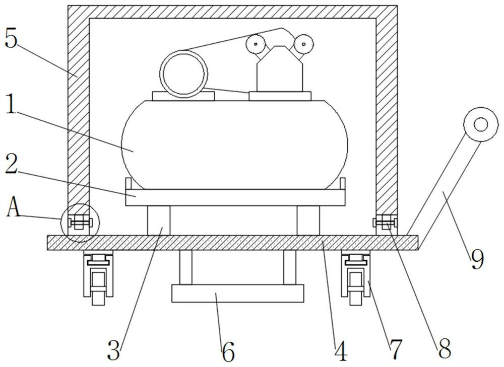
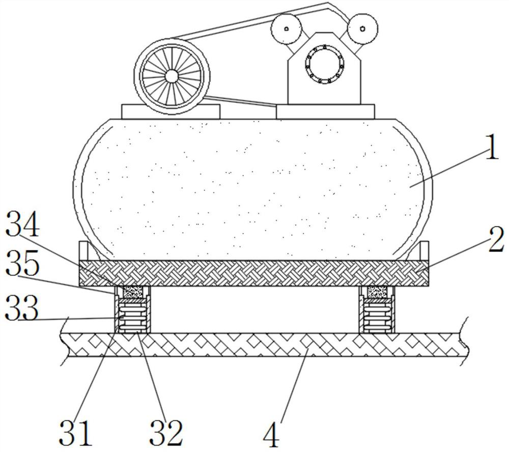
[0028] Such as Figure 1-5 As shown, the present invention provides an air compressor device used in a power system, including an air compressor body 1, a fixed plate 2 is fixedly installed on the bottom of the air compressor body 1, and a shock absorbing assembly is arranged on the bottom of the fixed plate 2 3. The bottom of the shock absorbing assembly 3 is provided with a stable base 4, the bottom of the stable base 4 is provided with a fixed assembly 6, the upper part of the stable base 4 is provided with a connecting assembly 8, the upper part of the connecting assembly 8 is provided with a protective cover 5, and the shock absorbing assembly 3 includes the installation sleeve 31, the interior of the installation sleeve 31 is fixedly installed with a shock-absorbing elastic column 32, the outside of the shock-absorbing elastic column 32 is provided with a buffer spring 33, the upper part of the buffer spring 33 is fixedly installed with a connecting block 34, and the uppe...

Embodiment 2

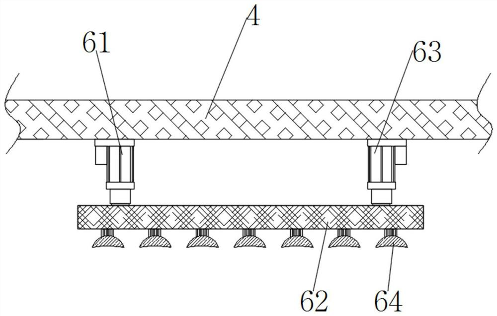
[0030] Such as Figure 1-5 As shown, on the basis of Embodiment 1, the present invention provides a technical solution: preferably, the fixing assembly 6 includes a first miniature electric telescopic rod 61, and the first miniature electric telescopic rod 61 is fixedly installed on the lower part of the stable base 4, The bottom of the first miniature electric telescopic rod 61 is provided with a stable pressing plate 62, the bottom of the stable pressing plate 62 is fixedly equipped with a suction cup 64, and the top of the stable pressing plate 62 is fixedly installed with a second miniature electric telescopic rod 63, away from the second miniature electric telescopic rod 63 The left side of the left side is provided with a first miniature electric telescopic rod 61, and the upper part of the second miniature electric telescopic rod 63 is fixedly connected with a stable base 4. When the air compressor body 1 is placed by setting the fixing assembly 6, the first miniature el...

Embodiment 3

[0032] Such as Figure 1-5As shown, on the basis of Embodiment 1, the present invention provides a technical solution: preferably, the connecting assembly 8 includes a connecting seat 81, the connecting seat 81 is fixedly installed on the upper part of the stable base 4, and the lower part of the protective cover 5 is fixedly installed with The connecting block 82, the inside of the connecting seat 81 and the inside of the connecting block 82 are provided with a transverse rectangular groove 83, the outer wall of the connecting block 82 is flexibly connected with the inside of the connecting seat 81, and the left side of the connecting seat 81 is provided with a threaded groove 84, the internal screw thread of threaded groove 84 is connected with threaded cap 86, and the internal activity of transverse rectangular groove 83 is equipped with circular connecting rod 85, and the left side of circular connecting rod 85 is fixedly installed with threaded cap 86, and the circular con...


PUM


Abstract

The invention discloses air compressor equipment for an electric power system, and relates to the technical field of air compressors, the air compressor equipment comprises an air compressor body, a fixing plate is fixedly mounted at the bottom of the air compressor body, a damping assembly is arranged at the bottom of the fixing plate, and a stable base is arranged at the bottom of the damping assembly; a fixing assembly is arranged at the bottom of the stable base, a connecting assembly is arranged on the upper portion of the stable base, and a protective cover is arranged on the upper portion of the connecting assembly. By arranging the damping assembly, when the air compressor body is subjected to pressure, a connecting block at the bottom of a fixing plate applies force to a damping elastic column and a buffer spring, so that the damping elastic column and the buffer spring in a mounting sleeve deform, and the buffering and damping effects are achieved; and the air compressor body is effectively protected, and the connecting assembly is arranged, so that the function of being convenient to disassemble is achieved while protection is achieved.

Description

technical field [0001] The invention relates to the technical field of air compressors, in particular to air compressor equipment used in power systems. Background technique [0002] An air compressor is a device used to compress gas. Air compressors are similar in construction to water pumps. Most air compressors are reciprocating piston, rotary vane or rotary screw. Before starting, first start the oil pump control system. After the oil pump control system is started, ensure that the lubricating parts of the air compressor are well lubricated. At the same time, the oil pump control system can adjust the internal oil pressure and oil temperature through the built-in temperature control valve to meet the needs of the system. When the compressor is working, the air is sucked through the self-cleaning air filter, and the filter is automatically cleaned by PLC. The air enters the first stage of compression after being automatically adjusted by the inlet guide vane. After the ...

Claims


Application Information

Patent Timeline
Patent Type & Authority Applications(China)
IPC IPC(8): F16M3/00F16B47/00F16F15/04F04B39/00F04B35/06
CPCF16M3/00F16B47/00F16F15/04F04B39/0044F04B35/06
Inventor 胡波严婵李红梅
Owner 浙江易泽信息科技有限公司
Why Eureka
Try Eureka