Underground water level observation device for hydrogeology

A technology for water level observation and hydrogeology, which is applied in measuring devices, lubrication indicating devices, liquid/fluid solid measurement, etc. It can solve problems such as easy shaking of probes and achieve the effect of improving accuracy

Pending Publication Date: 2022-04-26
叶薇
View PDF1 Cites 4 Cited by
  • Summary
  • Abstract
  • Description
  • Claims
  • Application Information

AI Technical Summary

Benefits of technology

This patented technology allows an observing device (such as a hydrophone) to measure seismic waves accurately without getting stuck between other parts like pump boxes due to vibrations caused by sea currents. By placing a weighted tank called a counterbox below the oil level within the observatory's borehole, there is no direct physical interaction between these components while still allowing them work together smoothly. Additionally, this design helps keep any foreign objects out of sight, reducing errors associated with measurements made over long periods of time. Overall, this technical effect improves the reliability and performance of oceanographic exploration operations.

Problems solved by technology

This patented technical problem addressed in this patent relates to improving the accuracy and reliability of observers' measurements when inserting probes inside monitoring wells for detecting groundwater conditions such as ponds, lakes, rivers, etc., particularly during long periods where they may have been exposed without being observed.

Method used


Image

  • Underground water level observation device for hydrogeology
  • Underground water level observation device for hydrogeology
  • Underground water level observation device for hydrogeology

Examples


Embodiment Construction

[0031] The following description serves to disclose the present invention to enable those skilled in the art to carry out the present invention. The preferred embodiments described below are only examples, and those skilled in the art can devise other obvious variations.

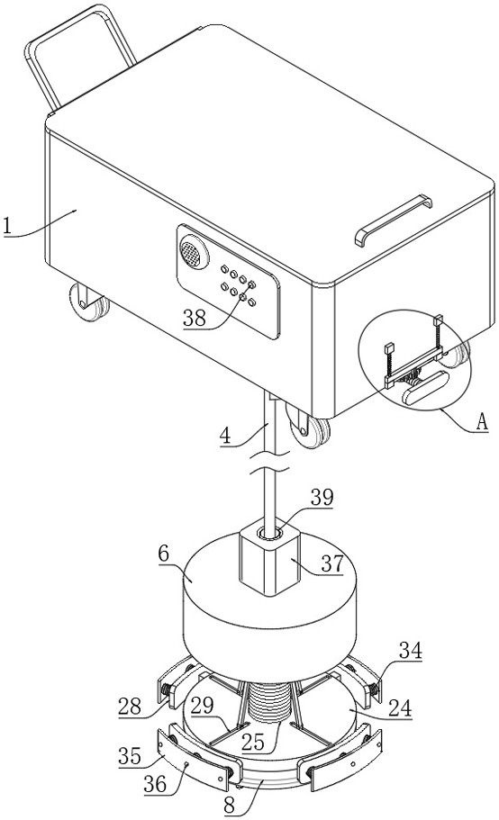
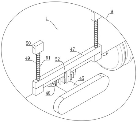
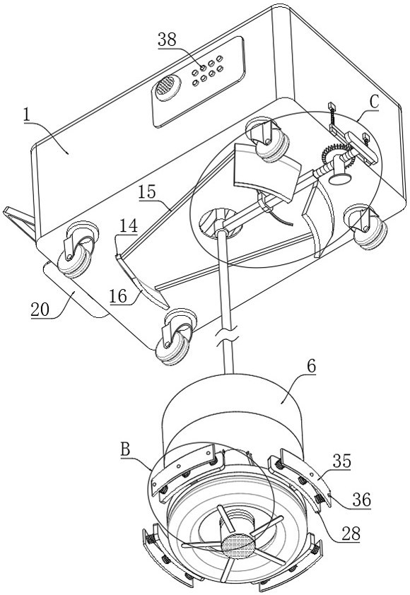
[0032] Such as Figure 1 to Figure 10 The shown hydrogeological groundwater level observation device includes an observation box 1, a storage battery 2 is fixed on the inner bottom surface of the observation box 1, a threading hole 3 is opened on the bottom surface of the observation box 1, and a measuring device is inserted inside the threading hole 3. Rope 4, a conductive wire 5 is inserted in the middle of the measuring rope 4, a counterweight box 6 is fixed on the bottom of the measuring rope 4, a probe 7 is fixed on the bottom surface of the counterweight box 6, and the probe 7 is electrically connected to the conductive wire 5; the top of the measuring rope 4 After extending into the inside of the obs...


PUM


Abstract

The invention relates to the technical field of water level observation, in particular to an underground water level observation device for hydrogeology, which comprises an observation box, a storage battery is fixed on the inner bottom surface of the observation box, a threading hole is formed in the bottom surface of the observation box, a measuring rope is inserted in the threading hole, a conductive wire is inserted in the middle of the measuring rope, and the conductive wire is connected with the storage battery. A weight box is fixed to the bottom of the measuring rope, a probe is fixed to the bottom face of the weight box, and the probe is electrically connected with the electric lead; according to the scheme, the top end and the bottom end of the measuring rope are positioned through the top positioning mechanism and the bottom positioning mechanism, inaccurate measurement caused by shaking of the bottom end of the measuring rope at the well bottom can be prevented, the measuring rope can be always kept in the middle of the measuring well, the measuring rope does not make contact with the inner wall of the measuring well, and the measuring accuracy is improved. The situation that the measuring rope is bent due to the fact that the measuring rope is jacked by obstacles such as broken stones or protrusions on the inner wall of the measured well is avoided, and the measuring precision is further improved.

Description


Claims


Application Information

Patent Timeline
Owner 叶薇
Why Eureka
Try Eureka