
Aperture device, image capturing mechanism and electronic equipment

An electronic device and aperture technology, which is applied in aperture, optics, camera, etc., can solve the problems of high power consumption, heavy weight, and complex structure of the aperture device, and achieve the effect of low power consumption, simple structure, and light weight

Active Publication Date: 2022-04-26
HONOR DEVICE CO LTD
View PDF8 Cites 0 Cited by
  • Summary
  • Abstract
  • Description
  • Claims
  • Application Information

AI Technical Summary

Problems solved by technology

This kind of aperture device has complex structure, heavy weight, and high power consumption, which cannot meet the needs of portable, light weight, and durable batteries for electronic equipment.

Method used


Image

  • Aperture device, image capturing mechanism and electronic equipment
  • Aperture device, image capturing mechanism and electronic equipment
  • Aperture device, image capturing mechanism and electronic equipment

Examples


no. 1 example

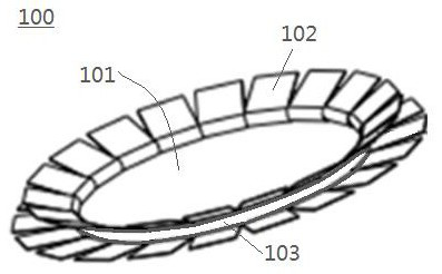
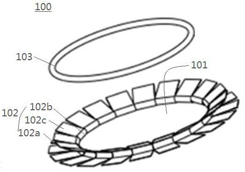
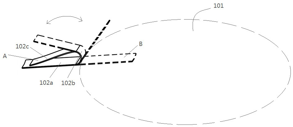
[0050] Please refer to Figure 1-Figure 11 , figure 1 It is a schematic diagram of the first embodiment of the aperture device; figure 2 It is a disassembled diagram of the first embodiment of the aperture device; image 3 and Figure 4 They are schematic diagrams of the two arrangements of the single sheet shielding part of the first embodiment of the aperture device; Figure 5 , Figure 6 , Figure 7 and Figure 8 They are schematic diagrams of several assembly methods of the sheet-shaped shielding part and the heating part of the first embodiment of the aperture device; Figure 9 It is a schematic diagram showing that the first end area of ​​the sheet-shaped shielding part of the first embodiment of the aperture device is installed on the end face of the lens barrel; Figure 10 It is a schematic diagram showing that the first end region of the sheet-shaped shielding part of the first embodiment of the aperture device is installed on the inner peripheral wall of the ...

no. 2 example

[0062] Please refer to Figure 12-Figure 17 , Figure 12 It is the front view of the cylindrical shielding part before and after torsional deformation of an implementation mode of the second embodiment of the aperture device; Figure 13 The left and right figures in the Figure 12 The top view of the left and right figures in the middle; Figure 14 for Figure 12 A schematic diagram showing that the first end region of the cylindrical shielding part is installed on the inner peripheral wall of the lens barrel; Figure 15 It is the front view before and after the torsional deformation of the cylindrical shielding part of another embodiment of the second embodiment of the aperture device; Figure 16 The left and right figures in the Figure 15 The top view of the left and right figures in the middle; Figure 17 for Figure 15 A schematic diagram of the shown first end region of the cylindrical shielding portion being installed on the end face of the lens barrel.

[0063]...


PUM


Abstract

The embodiment of the invention discloses an aperture device, an image capturing mechanism and electronic equipment. The electronic device can be a mobile phone, a tablet personal computer, a handheld computer, an interphone, a POS machine, an automobile data recorder, a wearable device, a virtual reality device, a vehicle-mounted front part and other terminal products with screens. The aperture device provided by the embodiment of the invention comprises a light through hole, a shielding part and a heating part, the shielding part is provided with a thermal deformation area, and the heating part is used for heating the thermal deformation area; the thermal deformation area is made of a shape memory material, the shape of the thermal deformation area can be changed under the thermal driving effect of the heating part and after the thermal driving effect is eliminated, the shielding area of the shielding part on the light through hole is changed through the shape change of the thermal deformation area, and therefore the aperture value is changed. The aperture device provided by the embodiment of the invention is simple in structure, light in weight and low in power consumption, and can meet the requirements of portability, light weight, battery durability and the like of the electronic equipment when being applied to an image capturing mechanism of the electronic equipment.

Description

technical field [0001] The present application relates to the technical field of electronic products, and in particular to an aperture device, which can be applied to electronic equipment equipped with an image-taking mechanism. Background technique [0002] With the rapid development of electronic products, the functional requirements of the imaging mechanism of electronic products are getting higher and higher. Allowing the aperture value of the aperture device of the imaging mechanism to be adjustable is a powerful means to enhance the competitiveness of electronic products. [0003] At present, the aperture device of the imaging mechanism on the market mainly drives a group of blades to rotate in a plane through a motor to change the blocking area of ​​the blades on the light hole, thereby changing the aperture value. This kind of aperture device has complex structure, heavy weight, and high power consumption, which cannot meet the requirements of portable, light weight...

Claims


Application Information

Patent Timeline
Patent Type & Authority Applications(China)
IPC IPC(8): G03B9/02
CPCG03B9/02
Inventor 矫利闯屈艳军
Owner HONOR DEVICE CO LTD
Learn More