Mean filtering method and system
A mean value filtering and mean value technology, applied in the field of mean value filtering methods and systems, can solve the problems of indistinguishable defects, missed product detection, false detection, etc., and achieve the effect of good pre-processing effect.
Pending Publication Date: 2022-04-26
昂视智能(深圳)有限公司
0 Cites 0 Cited by
AI-Extracted Technical Summary
Problems solved by technology
The disadvantages of this kind of processing are as follows. First, the processing area can only be a rectangle or the whole image, and the effect is not good for processing complex images with arbitrary shapes.
The second is that because the image boundary is processed by filling pixels, when proc...
Abstract
The invention discloses a mean filtering method and system. The method comprises the following steps: S1, obtaining a detection area image, a filtering kernel width and a filtering kernel height; s2, traversing pixel points of a to-be-detected area in the detection area image; s3, taking the current pixel point as an anchor point, establishing a rectangular detection frame with the width of a filtering kernel and the height of the filtering kernel, traversing pixel coordinates in the rectangular detection frame, judging whether the pixel coordinates are in an area needing to be detected or not, and if yes, executing S4; if not, traversing the next pixel coordinate; s5 is executed until the rectangular detection frame of one pixel point is traversed; s4, accumulating the pixel gray value and the point number of the pixel coordinate to obtain a total pixel gray value and a total point number; and S5, dividing the total pixel gray value by the total point number to obtain a mean value until the pixel points of the area needing to be detected are traversed to obtain a mean value map. According to the method, the area needing to be detected at any position and in any shape can be flexibly set, the influence of other images outside the area and the boundary is avoided, and a good pretreatment effect is achieved.
Application Domain
Image enhancementImage analysis
Technology Topic
Computer visionPattern recognition +2
Image
Examples
- Experimental program(1)
Example Embodiment
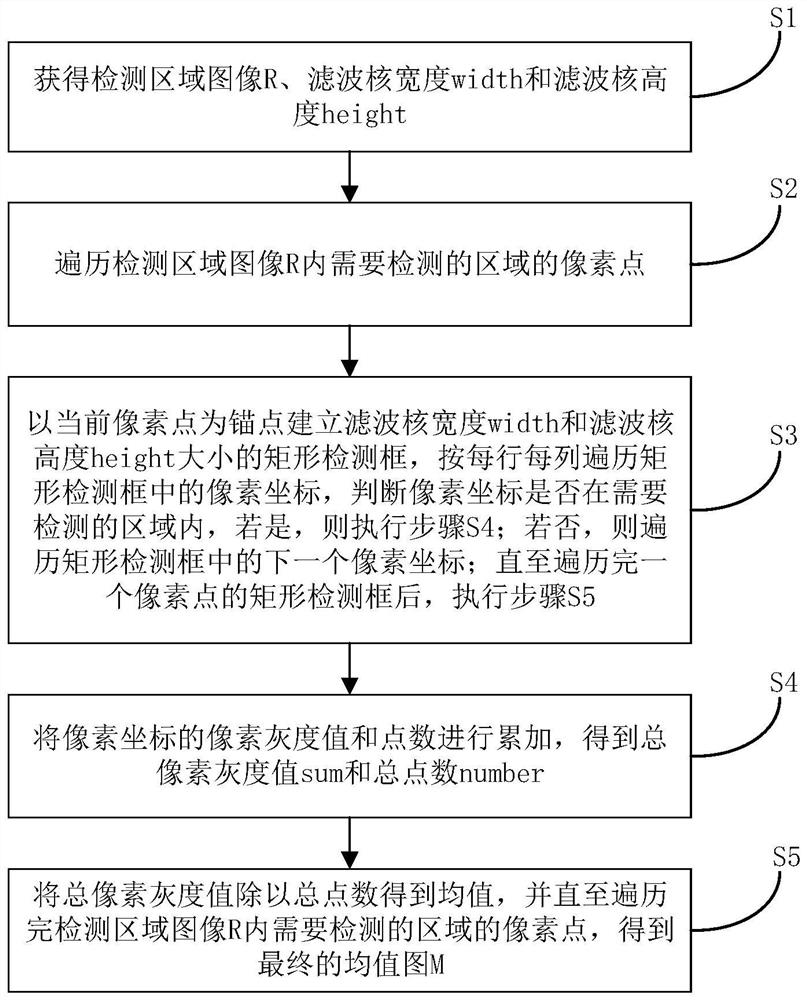
[0041] In order to have a clearer understanding of the technical features, objects and effects of the present invention, specific embodiments of the present invention are described in detail with reference to the accompanying drawings.
[0042] It should be noted that the flowchart shown in the drawings is only an exemplary description, not all content and operations / steps must be included, nor must it be performed in the order described. For example, some actions/steps can be decomposed, while some actions/steps can be merged or partially merged, so the actual order of execution may change according to the actual situation.
[0043] The block diagram shown in the drawings is only a functional entity and does not necessarily correspond to a physically separate entity. I.e., these functional entities may be implemented in the form of software, or implemented in one or more hardware modules or integrated circuits, or implemented in different networks and / or processor devices and / or microcontroller devices to implement these functional entities.
[0044] In the field of industrial automation machine vision, the demand for product defect detection is relatively large and the scene is relatively complex, the detection area of the product may be arbitrary or changeable, if only the rectangular detection area is used to do processing is far from enough, so it is necessary to consider any position of any shape of the detection area as a processing area, such as Figure 2 (b) shown, is a common circuit board, in which only need to detect defects in the white polygon box area of the product diagram (indicated by the "actual inspection area" below), the defect is marked as two places of white circle. The general processing process is to first convert the original color graph to a gray map, and then process the gray scale plot through mean filtering to obtain the mean plot, and then use the gray map to subtract the mean plot to obtain the difference plot, and finally the difference plot is processed out by binaryization. In fact, only the difference in the step of mean filtering processing has a greater impact on the final result, so only the mean filtering method needs to be optimized and improved to achieve good results. If you directly use the mean filtering method of the image library opencv, you need to take the smallest external parallel rectangle of the actual detection area as the region of interest of the image, such as Figure 3 (b) The white rectangle is its detection area, which will also process the place outside the actual detection area, such as Figure 3 (d) For images processed by mean filtering methods, it can be seen that places outside the actual detection area have also become blurred, which is not needed. Also, such as Figure 3 (e) (f) As shown, although the opencv method can process the defects in the actual detection area after processing, when processing boundary pixels, it will be affected by pixels outside the actual detection area, causing a circle of pixels with the same gray level as the defects, which will mistake these pixels for defects, and these pixels will be connected with the real defects on the boundary, which will cause missed detection and false detection of the product. Regardless of whether the opencv mean filter uses a filter kernel size setting large or small, there is no good effect, such as Figure 3 As shown in the renderings of the large filter kernel processing, although the defects are detected, there is too much boundary interference, such as Figure 4 As shown, in order to set up a small filter core processing rendering, although the boundary impact becomes smaller, the real defect defect cannot be processed, and the actual defect is connected with the boundary interference, resulting in the actual defect cannot be extracted. Combining the above factors, the present invention designs a mean filtering method, such as Figure 2 As shown, the method only needs to process the actual detection area, will not be affected by pixels outside the image and the actual detection area, and can effectively detect defects, the advantages of this method are the following points:
[0045] 1. The user can set any position and any shape of the detection area according to the detection needs, unlike the traditional detection method, which can only detect the rectangular area or the full map detection.
[0046] 2. The pixels on the boundary of the detection area will not be affected by other images outside the detection area and outside the boundary, and the defects on the boundary can be accurately found, and the false detection and omission of the boundary pixels will not be caused.
[0047] 3. For defects in a large area or a small area in the product, there are better detection effects.
[0048] Specifically, such as Figure 1 As shown, the present invention discloses a mean filtering method, in particular in the detection of industrial defects, such as electronic circuit board detection, screen scratch detection, mobile phone cover scratch detection, automotive power battery pit detection, tile crack detection, welding quality inspection, dispensing quality inspection and the like. The method consists of the following steps:
[0049] Step S1: Obtain the detection area image R, filter core width width and filter core height height through external input;
[0050] Step S2: Traverse the pixels of the area to be detected within the detection area image R;
[0051] Step S3: Take the current pixel as the anchor point (abscissa r, vertical coordinate c), establish a rectangular detection box with filter core width width and filter core height height height, traverse the pixel coordinates (x, y) in the rectangular detection box according to each row and column, determine whether the pixel coordinates are in the area to be detected, if so, perform step S4; if not, traverse the next pixel coordinate in the rectangular detection box; until the rectangular detection box of one pixel point is traversed, step S5 is performed.
[0052] Among them, it is necessary to determine whether the pixel coordinates are in the area to be detected, including: determine whether the pixel gray value of the pixel coordinates is a preset value. In some embodiments, the preset value is 255, in some other embodiments, the preset may not be limited to 255.
[0053] Step S4: Accumulate the pixel gray value and the number of points of the pixel coordinates, as shown in Formula (1) and Formula (2), to obtain the total pixel gray value sum and the total number of points;
[0054]
[0055]
[0056] Step S5: If the cumulative number of points is 0, the mean value of the pixel gray value of the pixel point is 0, otherwise the total pixel gray value is divided by the total number of points to obtain the mean, and until the pixels of the area to be detected within the detection area image R are traversed, the final mean figure M is obtained, as shown in Formula (3). where the number of points is a variable with an initial value of 0, when iterating through a detection box with length width and width of height, if the current pixel coordinate point meets the requirements, the value of the number of points is added to 1;
[0057]
[0058] Step S6: Output mean Figure M.
[0059] Further, in the present embodiment, Step S1 further comprises obtaining a color source image to be processed G, i.e., a Figure 2 (a)。 Wherein, the steps to obtain the detection area image R, including:
[0060] In the original image G determines any location of any shape of the area to be detected, i.e., Figure 2 (b) The white polygon box shown, and the pixel gray value of the area to be detected is converted to a preset value, and the pixel gray value of other areas is converted to 0, and the detection area image R is obtained. Among them, the area to be detected in any position of any shape can be determined by the user manually traced, or automatically identified by the computer. In some embodiments, the preset value is 255, 255 is to be processed, 0 is not required to be processed. In some other embodiments, the preset may not be limited to 255.
[0061] Accordingly, step S2 comprises:
[0062] Step S21: Calculate the minimum external parallel rectangular area of the area to be detected within the detection area image R, and intercept it in the detection area image R.
[0063] Wherein, the interception is carried out in the detection area image R, comprising: according to the rectangular area and the original image G as the coordinate reference, the rectangular area is intercepted within the detection area image R.
[0064] Step S22: Traverse the pixels in the rectangular area to determine whether the pixels are in the area to be detected, if so, perform step S3, if not, iterate over the next pixel.
[0065] Among them, it is determined whether the pixel is in the area to be detected, including: determine whether the pixel gray value of the pixel is a preset value. In some embodiments, the preset value is 255, in some other embodiments, the preset may not be limited to 255.
[0066] In some embodiments, step S21 further comprises:
[0067] Step S20: Determine whether the proportion of the area to be detected in the R area image of the detection area is less than the threshold value of the R size of the detection area image, if so, record the pixels of the area to be detected, and perform steps S3, S4 and S5; if not, perform step S21. In some embodiments, the threshold may be 20%, in some other embodiments, the threshold may not be limited to 20%.
[0068] In some embodiments, step S3 further comprises:
[0069] Determine whether the pixel coordinates are beyond the rectangular area, and at the same time determine whether the pixel coordinates are in the area to be detected, if so, perform step S4; if not, iterate over the next pixel coordinate in the rectangle detection box.
[0070] In some other embodiments, in order to avoid pixel coordinates exceeding the rectangular region, step S3 further comprises:
[0071] The left and right boundaries of the rectangular area are extended out (width-1)/2 pixels, and the upper and lower boundaries are each extended out (height-1)/2 pixels, so that when the pixel coordinates of the rectangular detection box that traverse the current anchor point, there is no need to determine whether the pixel coordinates are beyond the rectangular area.
[0072] as Figure 5 As shown, the present invention discloses a mean filtering system, comprising:
[0073] Acquisition module for obtaining detection area image R, filter core width width and filter core height height through external inputs;
[0074] Traversal module for traversing the pixels of the area to be detected within the R of the detection area image;
[0075] Detection module, used to take the current pixel point as the anchor point (abscissa r, vertical coordinate c), establish a rectangular detection box with the width of the filter core width and height height of the filter core height, traverse the pixel coordinates in the rectangular detection box according to each row and column (x, y), determine whether the pixel coordinates are in the area to be detected, if so, perform the accumulation calculation module; if not, traverse the next pixel coordinate in the rectangular detection box; until the rectangular detection box of one pixel point is traversed, the mean calculation module is performed;
[0076] Among them, it is necessary to determine whether the pixel coordinates are in the area to be detected, including: determine whether the pixel gray value of the pixel coordinates is a preset value. In some embodiments, the preset value is 255, in some other embodiments, the preset may not be limited to 255.
[0077] The accumulation calculation module is used to accumulate the pixel gray value and the number of points of the pixel coordinates, as shown in formula (1) and formula (2), to obtain the total pixel gray value sum and the total number of points number;
[0078]
[0079]
[0080] Mean calculation module, for if the cumulative number of points is 0, the average value of the pixel gray value of the pixel point is 0, otherwise the total pixel gray value is divided by the total number of points to obtain the mean, and until the pixels of the area to be detected within the detection area image R are traversed, the final mean map M is obtained, as shown in formula (3). where the number of points is a variable with an initial value of 0, and when iterating through a detection box with width and width of height, the value of the number of points is increased by 1 if the current pixel coordinate point meets the requirements.
[0081]
[0082] Output module for output mean plot M.
[0083] Further, in the present embodiment, the obtained module, further for obtaining a color original image to be processed G, i.e., that is Figure 2 (a)。 Wherein, an image of the detection area R is obtained, including:
[0084] In the original image G determines any location of any shape of the area to be detected, i.e., Figure 2 (b) The white polygon box shown, and the pixel gray value of the area to be detected is converted to a preset value, and the pixel gray value of other areas is converted to 0, and the detection area image R is obtained. Among them, the area to be detected in any position of any shape can be determined by the user manually traced, or automatically identified by the computer. In some embodiments, the preset value is 255, 255 is to be processed, 0 is not required to be processed. In some other embodiments, the preset may not be limited to 255.
[0085] Accordingly, iterate over the pixels of the area to be detected within the detection area image R, including:
[0086] Calculate the minimum external parallel rectangular area of the area to be detected in the detection area image R, and intercept it in the detection area image R. Wherein, specifically, the interception is carried out within the detection area image R, comprising: according to the rectangular region and the original image G as the coordinate reference, the rectangular region is intercepted within the detection area image R;
[0087] Iterate over the pixels in the rectangular area to determine whether the pixels are in the area to be detected, if so, execute the detection module, and if not, traverse the next pixel. Among them, specifically, to determine whether the pixel is in the area that needs to be detected, including: determine whether the pixel gray value of the pixel is a preset value. In some embodiments, the preset value is 255, in some other embodiments, the preset may not be limited to 255.
[0088] In some embodiments, the calculation of the detection area image within the region to be detected within the region of the region to be detected, and intercepted within the detection area image R, further comprising:
[0089] Determine whether the proportion of the area to be detected in the R area image of the detection area is less than the threshold, if so, the pixels of the area to be detected can be recorded, and the detection module, the cumulative calculation module and the mean calculation module are performed; if not, the minimum external parallel rectangular area of the area to be detected in the detection area image R is calculated, and the interception is carried out in the detection area image R. In some embodiments, the threshold may be 20%, in some other embodiments, the threshold may not be limited to 20%.
[0090] In some embodiments, the detection module is also used to determine whether the pixel coordinates exceed the rectangular region, and at the same time determine whether the pixel coordinates are in the area to be detected, if so, the cumulative calculation module is performed; if not, the next pixel coordinate in the rectangular detection box is traversed.
[0091] In some other embodiments, in order to avoid pixel coordinates exceeding the rectangular area, the detection module is also used to extend the left and right boundaries of the rectangular area (width-1) / 2 pixels, the upper and lower boundaries each extended outward (height-1) / 2 pixels, such an advantage is that when iterating over the pixel coordinates of the rectangular detection box of the current anchor point, there is no need to judge whether the pixel coordinates exceed the rectangular area.
[0092] By implementing the present invention, having the following beneficial effects:
[0093] The present invention may be based on the actual detection needs of the user, flexibly set any position of any shape of the area to be detected, and the pixels on the boundary of the area to be detected will not be affected by other images outside the region and outside the boundary, regardless of whether the defects of the product are in the area that needs to be detected or on the boundary, the method can have a better pre-processing effect.
[0094] It will be appreciated that the above embodiments only express the preferred embodiment of the present invention, the description is more specific and detailed, but can not be understood as a limitation on the scope of the patent of the invention; it should be noted that for those of ordinary skill in the art, without departing from the concept of the present invention, the above technical features can be freely combined, and several deformations and improvements can also be made, which belong to the scope of protection of the present invention; therefore, where the scope of the claims of the present invention is equivalent to transformation and modification, should fall within the scope of the claims of the present invention.
PUM


Description & Claims & Application Information
We can also present the details of the Description, Claims and Application information to help users get a comprehensive understanding of the technical details of the patent, such as background art, summary of invention, brief description of drawings, description of embodiments, and other original content. On the other hand, users can also determine the specific scope of protection of the technology through the list of claims; as well as understand the changes in the life cycle of the technology with the presentation of the patent timeline. Login to view more.