

Dual circularly polarized antenna elements and dual circularly polarized front antennas
A dual-circular polarization and antenna unit technology, which is applied to antenna arrays, individually powered antenna arrays, antennas, etc., can solve the problems of difficulty in realizing planar dual-circular polarization of multi-layer board structures, complex structures, and high technological difficulties, and achieves The effect of reducing the number of layers and punching holes, meeting process requirements, and breaking through process limitations
Active Publication Date: 2022-05-31
CHENGDU T-RAY TECH CO LTD
View PDF12 Cites 0 Cited by
- Summary
- Abstract
- Description
- Claims
- Application Information
AI Technical Summary
Problems solved by technology
This method can achieve dual circular polarization, but there are also many limitations, mainly because dipole antennas mostly use probe feeding, the structure is complex, the process is difficult, and it is difficult to realize the planar dual circular polarization function of the multilayer board structure.
Method used
View moreImage
Smart ImageViewing Examples

Examples
no. 1 example
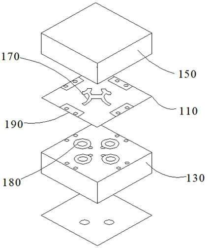
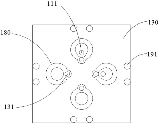
[0038] In this embodiment, the second radio frequency microwave plate 130 is also provided with a second conductive via that penetrates to the radiation patch 180
[0039] It should be noted that, in this embodiment, the first conductive hole is a feeding hole, and the second conductive hole is a short-circuit metal via hole,
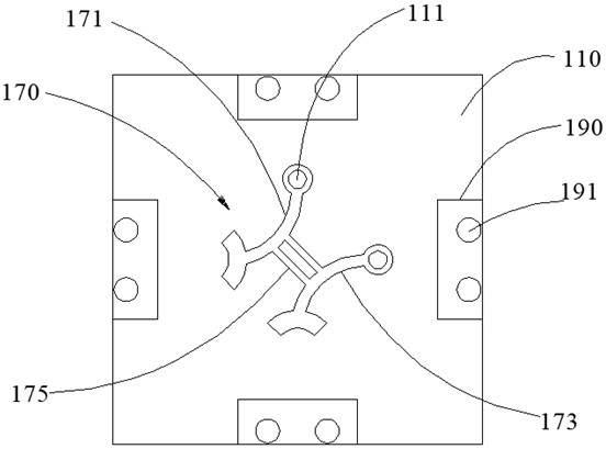
[0041] The bicircular pole bridge 170 includes a first bridge section 171, a second bridge section 173 and a connecting section 175. The first bridge section 171
[0048] In this embodiment, the coupling patch 190 is provided with a third conductive via 191, and the third conductive via 191 at least penetrates
no. 2 example
Login to View More PUM
 Abstract
Embodiments of the present invention provide a dual circularly polarized antenna unit and a dual circularly polarized front antenna, which relate to the field of antenna technology. The dual circularly polarized antenna unit includes a first radio frequency microwave board, a second radio frequency microwave board, a dual Circular pole bridge and radiation patch, the present invention adopts the structure of multilayer board with metal vias, realizes the planar double circular polarization function of the multilayer board structure, and sets the double circular pole bridge and radiation patch respectively on the At the same time, the quasi-coaxial structure of the input end is achieved by drilling holes on the first radio frequency microwave board, which breaks through the technological limitations and makes the drilling method available in the Ka and above frequency bands, which meets the technological requirements and simplifies the process. structure, which solves the feeding problem.
Description
Dual circularly polarized antenna elements and dual circularly polarized front antennas technical field The present invention relates to antenna technology field, specifically, relate to a kind of double circularly polarized antenna unit and double circularly polarized array surface antenna. Background technique [0002] As the requirements of the communication system for signal bandwidth and signal rate gradually increase, the requirements for terminal antennas are also increasing. higher. Replacing traditional parabolic antennas with low-cost phased array antennas has recently shown great advantages, but phased array antennas have The performance drops more on large-angle scanning, which has a great impact on the overall usage. [0003] Tightly coupled antennas are an effective measure to solve the degradation of large-angle scanning performance. Most of the current tightly coupled antennas Only single-line polarization or dual-line polarization is studied, while c...
Claims
Login to View More Application Information
Patent Timeline
 Patent Type & AuthorityPatents(China)
IPC IPC(8): H01Q1/38H01Q1/50H01Q21/06
CPCH01Q1/38H01Q1/50H01Q21/061
Inventor颜微吴祖兵王新辉
OwnerCHENGDU T-RAY TECH CO LTD