Stirring mechanism and dough mixer with same
A technology of mixing mechanism and dough groove, which is used in dough mixers, structural parts of mixing/kneading machines, mixing/kneading with vertical installation tools, etc. , does not meet the steps and other problems, to achieve the effect of adding water briefly
- Summary
- Abstract
- Description
- Claims
- Application Information
AI Technical Summary
Problems solved by technology
Method used
Image
Examples
Embodiment 1
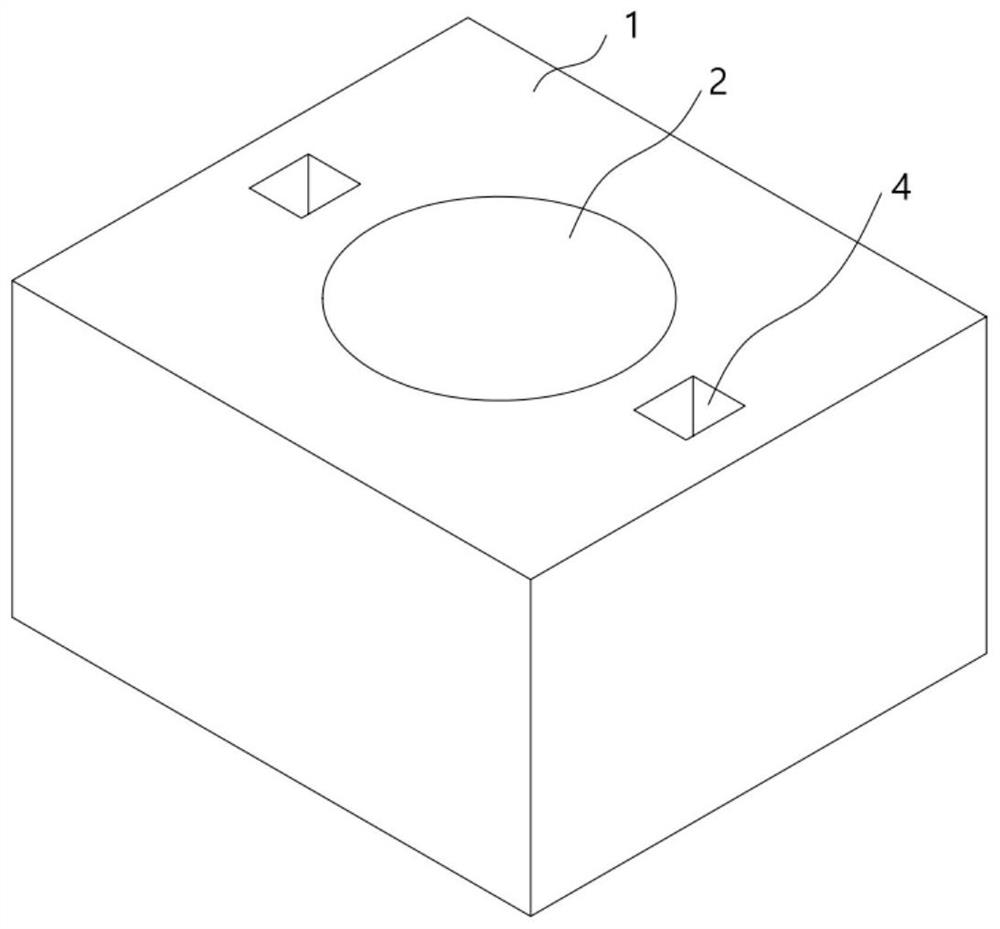
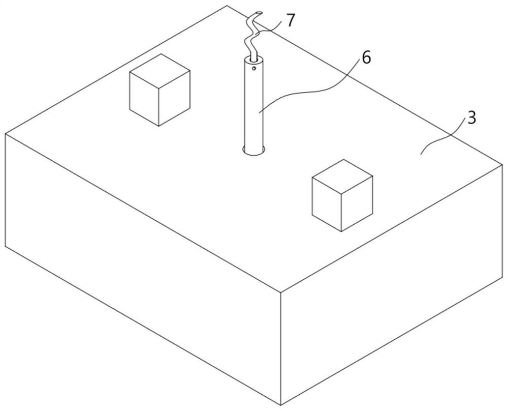
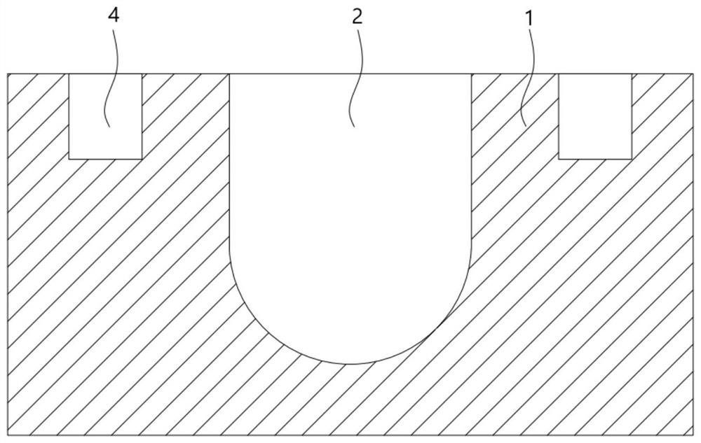
[0039] A stirring mechanism includes a base 1, and a dough mixing groove 2 for placing flour is opened inside the base 1, and the dough mixing groove 2 is an open groove with an upward opening for placing subsequent flour, and stirring is also performed inside the dough mixing groove 2. , the bottom of the kneading tank 2 is arc-shaped, which is convenient for subsequent stirring. The base 1 is located on both sides of the kneading tank 2 with limit slots 4 for the cover plate 3 to be movably inserted. In this embodiment, the limit slots 4 are two Each of them is respectively opened on both sides of the kneading groove 2, or there may be more than one. In this embodiment, no expansion is made. The limit groove 4 is a square groove. When the cover plate 3 is inserted into the limit groove 4, the kneading groove 2 Cover, the lower part of the cover plate 3 has two square protrusions corresponding to the surface groove 2. When the square protrusions of the cover plate 3 are put in...
Embodiment 2
[0045] On the basis of the first embodiment, the structure of the inflatable assembly in the second embodiment is disclosed. The inflatable assembly includes an inflatable box 17 fixedly arranged inside the installation cavity 8 , a piston plate 18 is movably arranged inside the inflatable box 17 , and inside the inflatable box 17 It is hollow, the piston plate 18 and the inner wall of the air box 17 form a closed space. When the piston plate 18 moves downward, it can squeeze the gas inside the air box 17, and squeeze the gas inside the air box 17 into the air collecting cavity 27. A first elastic block 19 is fixedly connected to the inner wall of the piston plate 18 and the inflatable box 17 , a track groove 20 is opened above the inflatable box 17 , and a track block 21 that is in active contact with the toggle rod 11 is arranged inside the track groove 20 , and the track block 21 is movable. It is arranged inside the track groove 20. During the rotation of the toggle lever 1...
Embodiment 3
[0048] The water blocking assembly includes a gas collection chamber 27 that is opened inside the cover plate 3 and communicated with the inflatable box 17. A second one-way valve 28 is provided at the connection between the inflatable box 17 and the gas collection chamber 27, and the second one-way valve 28 ensures the gas The inside of the gas collection chamber 27 can only be entered from the inside of the inflatable box 17. A piston block 29 is movably arranged inside the gas collection chamber 27. The piston block 29 and the inner wall of the gas collection chamber 27 form a closed space, and the gas entering the gas collection chamber 27 can The piston block 29 is driven to move to the left, a third elastic block 291 is fixedly connected to the piston block 29 and the inner wall of the gas collection chamber 27 , and a water blocking chamber 30 is opened inside the cover plate 3 , and the water blocking chamber 30 passes through the first air passage 31 and the gas collect...
PUM
 Abstract
Description
Claims
Application Information
 - R&D
- Intellectual Property
- Life Sciences
- Materials
- Tech Scout
- Unparalleled Data Quality
- Higher Quality Content
- 60% Fewer Hallucinations
Browse by: Latest US Patents, China's latest patents, Technical Efficacy Thesaurus, Application Domain, Technology Topic, Popular Technical Reports.
© 2025 PatSnap. All rights reserved.Legal|Privacy policy|Modern Slavery Act Transparency Statement|Sitemap|About US| Contact US: help@patsnap.com


