Device for realizing full-automatic scanning of test tubes

A fully automatic, test-tube technology, applied in the field of medical devices, can solve the problems of difficulty in ensuring scanning accuracy, high time and labor costs, and overwhelmed medical staff, so as to ensure timeliness and accuracy, reduce time, and ease work. effect of stress

Inactive Publication Date: 2022-04-29
自贡市第一人民医院
View PDF0 Cites 0 Cited by
  • Summary
  • Abstract
  • Description
  • Claims
  • Application Information

AI Technical Summary

Problems solved by technology

[0003] For the extremely busy clinical front-line nursing work, medical staff need to spend a lot of time scanning test tubes, and the time and labor costs required for routine manual scanning of 4200 times a day are too high
Especially when encountering emergencies that require larger batches of collection in a short period of time, medical staff are often overwhelmed, and when the number of test tubes is too large, it is difficult to guarantee the accuracy of manual scanning

Method used


Image

  • Device for realizing full-automatic scanning of test tubes
  • Device for realizing full-automatic scanning of test tubes
  • Device for realizing full-automatic scanning of test tubes

Examples


Embodiment

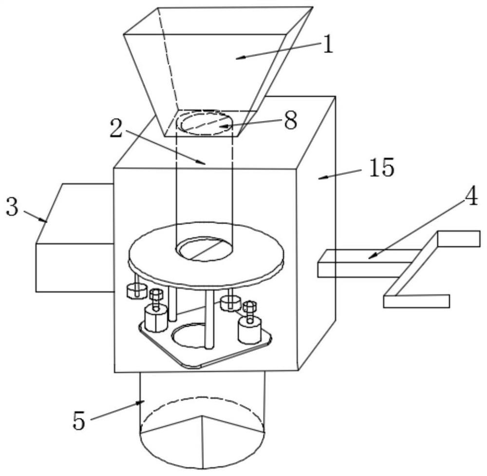
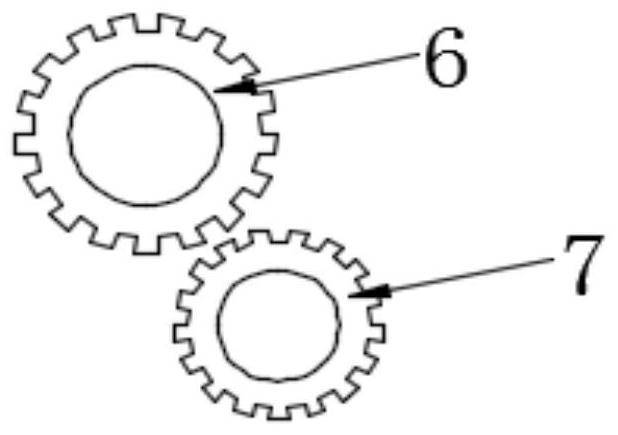
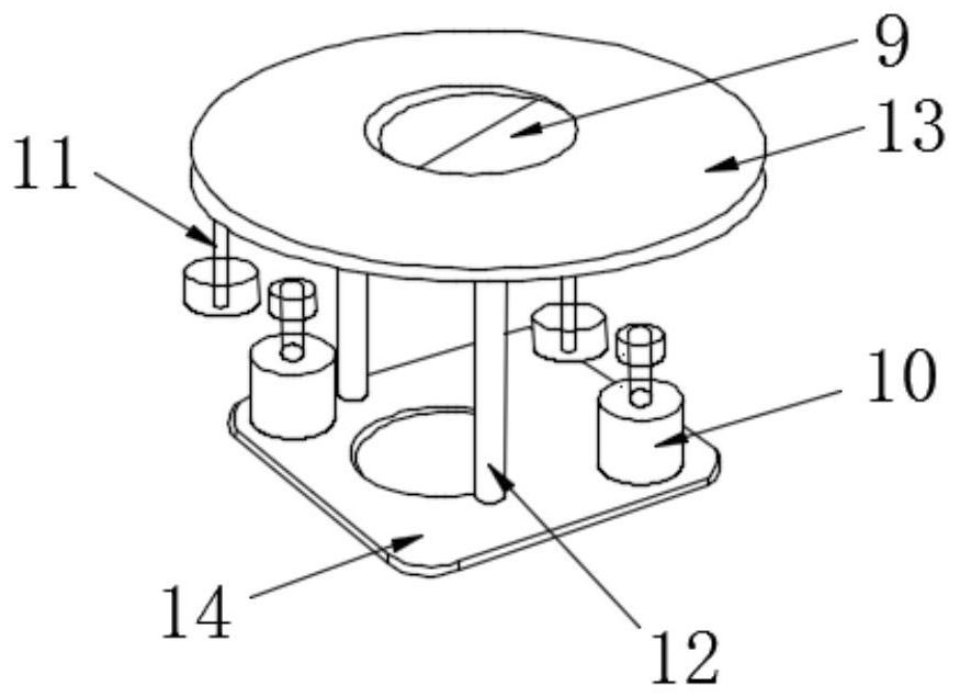
[0044] Such as figure 1 , figure 2 and Figure 5 As shown, the embodiment of the present application provides a device for fully automatic scanning of test tubes, including a receiving chamber 1, a scanning chamber 15 and a receiving chamber 5 for receiving dropped test tubes after scanning. The storage cylinder 2 of the test tube, the top of the storage cylinder 2 is connected with the bottom end of the accommodation chamber 1, and the side of the scanning chamber 15 perpendicular to the storage cylinder 2 is provided with a clamping mechanism 4 for clamping the scanner; A rotating device for driving the storage cylinder 2 to rotate is provided. The rotating device includes a rotating plate 13, a rotating assembly and a placement plate 14. The rotating assembly includes a motor 10, a driving wheel 7, a driven wheel 6 and a connecting rod 11. The driving wheel 7 is fixedly installed On the transmission shaft of the motor 10, the motor 10 is fixedly connected with the upper ...

Embodiment approach

[0049] As a specific implementation, the control device 3 includes a power supply, a processor and a controller, the power supply is electrically connected to the processor, the processor is electrically connected to the controller, and the controller is electrically connected to the motor 10 . The start and stop of the motor 10 are controlled by the processor and the controller, so as to realize automatic scanning. The power supply can be a battery, or an external 220V indoor power supply. The processor can be a single-chip microcomputer series chip. As far as the controller is concerned, it changes the wiring of the main circuit or the control circuit and changes the resistance value in the circuit to control the start of the motor. The master device of speed regulation, braking and reverse can be used to control the motor 10 to start and stop.

[0050] Such as image 3 As shown, as a specific embodiment, two first semicircular cover plates are provided at the bottom end of...


PUM


Abstract

The invention discloses a device for realizing full-automatic scanning of a test tube, relates to the technical field of medical instruments, and solves the problem of how to realize automatic scanning of a blood collection tube. According to the technical scheme, a rotating device is arranged in a scanning cavity, and a rotating plate of the rotating device is connected with the top end of a storage cylinder; in this way, in the rotating process of the rotating assembly, the storage barrel can be driven to rotate, the scanner clamped by the clamping mechanism can just scan the test tubes in the rotating storage barrel, and the test tubes fall into the receiving cavity from the storage barrel after scanning is completed. According to the invention, automatic scanning of the test tube can be completed, the working pressure and working time of nursing personnel and medical personnel are reduced, the accuracy of blood sample test tube scanning is improved, and the sample inspection time is shortened; and timeliness and accuracy of timely inspection of a large number of specimens are ensured.

Description

technical field [0001] The invention relates to the technical field of medical equipment, more specifically, it relates to a device for realizing automatic scanning of test tubes. Background technique [0002] There are basically hundreds of long-term dialysis patients in the hemodialysis room of the hospital. According to the national SOP regulations, all patients need to complete routine blood tests every month. The hemodialysis room of each hospital has a daily dialysis volume of nearly hundreds of people, with 6-7 test tubes per person, and each test tube performs 2 scan registrations (1 sampling registration plus 1 inspection registration), in order to complete the final scan delivery. Go to the laboratory for follow-up examination. Assuming that the number of dialysis patients per day is 300, the workload of manual scanning is: 300*7*2=4200 scans / day. [0003] For the extremely busy clinical front-line nursing work, medical staff need to spend a lot of time scanning ...

Claims


Application Information

Patent Timeline
IPC IPC(8): A61B5/15G06K17/00
CPCA61B5/150786G06K17/0025
Inventor 赖凤英陈怡洁刘冰洁刘兰
Owner 自贡市第一人民医院
Why Eureka
Try Eureka