Breathing machine, breathing machine system and control method of breathing machine system

A ventilator and breathing tube technology, applied in the field of ventilators, can solve the problems of complex connection structure, unbalanced pressure in the ventilator system, and high manufacturing, debugging and maintenance costs, and achieve the effects of improving work ability, improving convenience, and low cost.

Inactive Publication Date: 2022-04-29
崔鼎
View PDF1 Cites 0 Cited by
  • Summary
  • Abstract
  • Description
  • Claims
  • Application Information

AI Technical Summary

Problems solved by technology

[0003] In the prior art, a ventilator is configured with multiple oxygen flow paths to simultaneously support respiratory treatment for multiple patients, such as "a multi-channel ventilator based on a pneumatic system" disclosed in the patent application number "202110226486.0", which Including: oxygen filter, air filter, controller and N breathing structures, multiple breathing structures work independently without affecting each other, which is conducive to improving the efficiency of the use of the ventilator and avoiding the waste of medical resources, but it independently sets the breathing structure , leading to high manufacturing, commissioning and maintenance costs, complex connection structures, and difficulty in effectively ensuring sufficient breathing gas supply to the patient when the breathing gas is circulating, and the pressure in the ventilator system is unbalanced

Method used


Image

  • Breathing machine, breathing machine system and control method of breathing machine system
  • Breathing machine, breathing machine system and control method of breathing machine system
  • Breathing machine, breathing machine system and control method of breathing machine system

Examples


Embodiment Construction

[0043] The embodiments of the present invention will be described in detail below with reference to the drawings in the embodiments of the present invention.

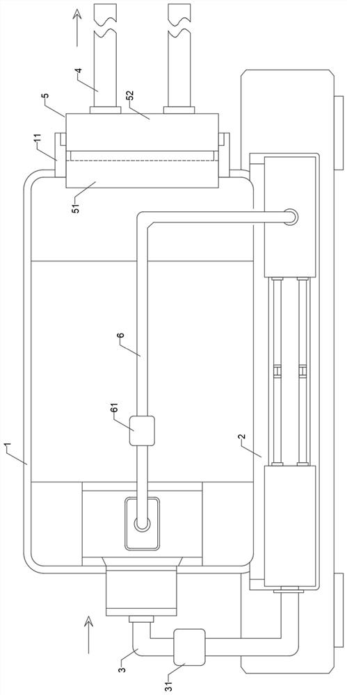
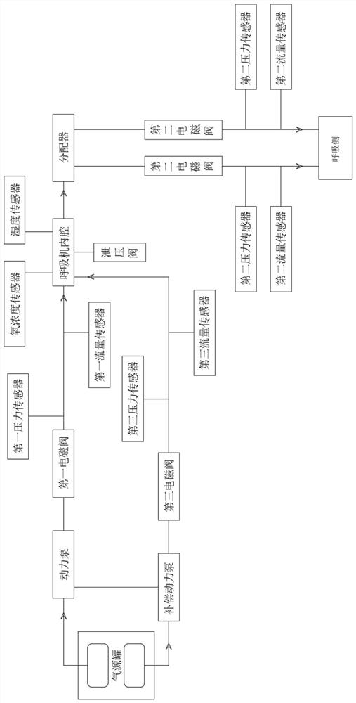
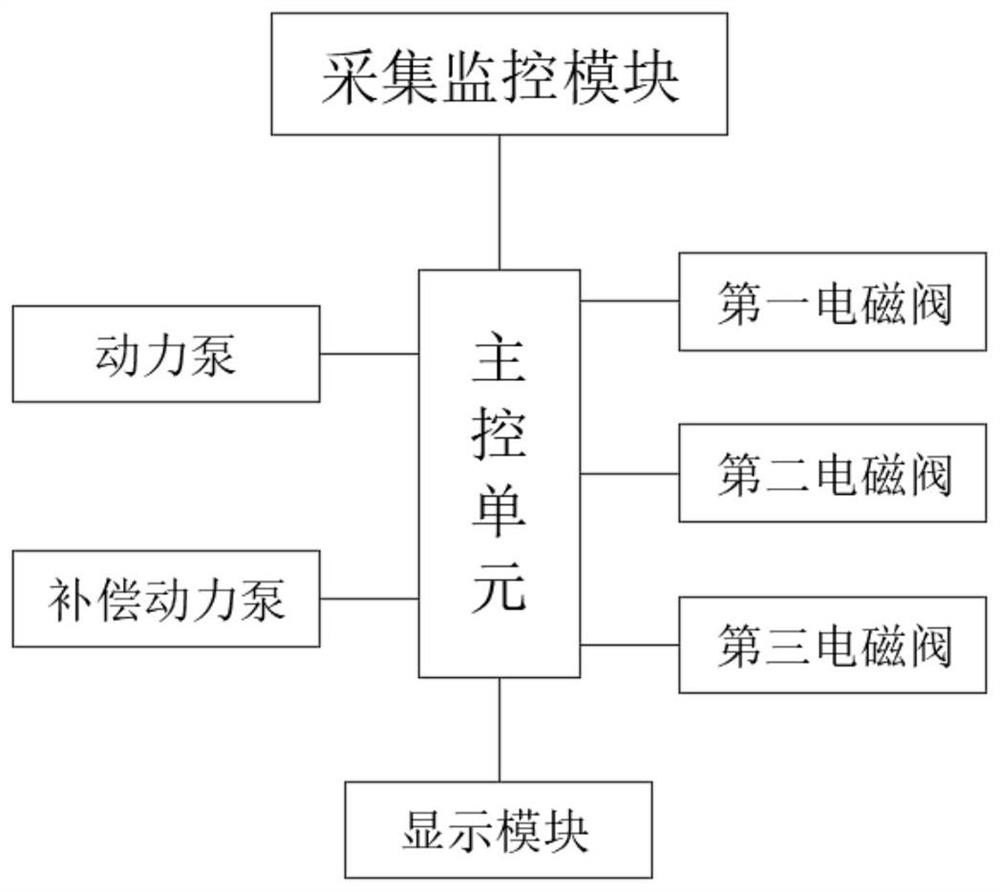
[0044] see Figure 1-Figure 5, this embodiment provides a ventilator system, which is applied to non-invasive respiration, assists medical treatment or alleviates respiratory symptoms of patients, which includes: ventilator 1, gas source tank 2, gas source input pipeline 3, breathing pipeline 4. Distributor 5, main control unit and acquisition monitoring unit;

[0045] The ventilator 1 has a sterile inner cavity, which can accommodate and collect breathing gas, and output it to the distributor 5 after confluence. The distributor 5 is arranged at the output end of the inner cavity of the ventilator 1, and the breathing pipeline 4 is provided with multiple channels. The multi-way breathing pipeline 4 is respectively sealed and connected to the output end of the distributor 5, and the breathing pipeline 4 is connected to ...


PUM


Abstract

The invention relates to a breathing machine, a breathing machine system and a control method thereof, the breathing machine system comprises a breathing machine, an air source tank, an air source input pipeline, a breathing pipeline, a distributor, a main control unit and an acquisition monitoring unit, and the breathing machine is provided with a sterile inner cavity; the air source tank is provided with at least two branch air source tanks, and the branch air source tanks are used for supplying breathing air; two end parts of the air source input pipeline are respectively in fluid connection with the branch air source tank and the inner cavity of the breathing machine; the distributor is arranged at the output end of the respirator inner cavity; the multiple breathing pipelines are connected to the output end of the distributor in a sealed mode. The main control unit configures and updates operation parameters of the breathing machine system; the collecting and monitoring unit monitors and feeds back the running state of the breathing machine system to the main control unit, and the collecting and monitoring unit is in coupling connection with the main control unit. Supply and circulation of sufficient breathing gas in the breathing pipeline are effectively guaranteed, meanwhile, a sharing mechanism of the breathing machine system is achieved, the utilization rate of resources of the breathing machine system is increased, and the cost is low.

Description

technical field [0001] The invention relates to the technical field of ventilators, in particular to a ventilator, a ventilator system and a control method thereof. Background technique [0002] Ventilator is a device that can replace, control or change people's normal physiological breathing, increase lung ventilation, improve respiratory function, reduce breathing work consumption, and save heart reserve capacity. It is widely used in respiratory failure due to various reasons, anesthesia respiratory management during major surgery, respiratory support therapy and emergency resuscitation. The ventilator includes an invasive ventilator and a non-invasive ventilator. The invasive ventilator is connected to the trachea of ​​the patient, and the non-invasive ventilator is usually connected to the breathing mask worn by the patient. [0003] In the prior art, a ventilator is configured with multiple oxygen flow paths to simultaneously support respiratory treatment for multiple...

Claims


Application Information

Patent Timeline
Patent Type & Authority Applications(China)
IPC IPC(8): A61M16/10A61M16/00
CPCA61M16/0003A61M16/024A61M16/10
Inventor 崔鼎李艳芝樊树荣管金兰
Owner 崔鼎
Why Eureka
Try Eureka