Cutting mechanism for pipe fitting cutting machine

A cutting mechanism and cutting machine technology, applied in maintenance and safety accessories, metal processing mechanical parts, manufacturing tools, etc., can solve the problems of pipe incision accuracy not meeting design requirements, manual grinding, and large vibration of the blade. Improve assembly stability, improve incision accuracy, and improve the effect of clamping effect

Active Publication Date: 2022-04-29
福建纳川管业科技有限责任公司 +1
View PDF12 Cites 0 Cited by
  • Summary
  • Abstract
  • Description
  • Claims
  • Application Information

AI Technical Summary

Problems solved by technology

A relatively large defect in this assembly method is that the cutting driving force is likely to be concentrated on the side of the cutter shaft with the side stopper, resulting in uneven force, so the blade during the cutting process has a large amount of vibration, resulting in pipe fitting The cutting precision cannot meet the design requirements, and manual grinding is often required after cutting

Method used


Image

  • Cutting mechanism for pipe fitting cutting machine
  • Cutting mechanism for pipe fitting cutting machine
  • Cutting mechanism for pipe fitting cutting machine

Examples


Embodiment Construction

[0035] In order to facilitate the understanding of those skilled in the art, the structure of the present invention will be further described in detail with the embodiments in conjunction with the accompanying drawings:

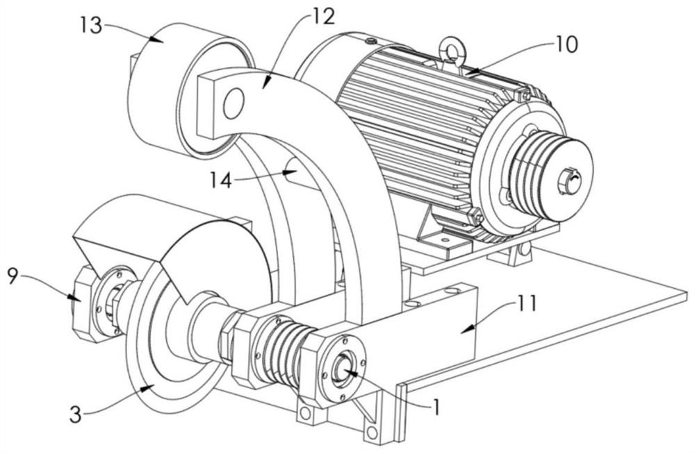
[0036] refer to Figure 1-9 , a cutting mechanism for a pipe cutting machine, comprising

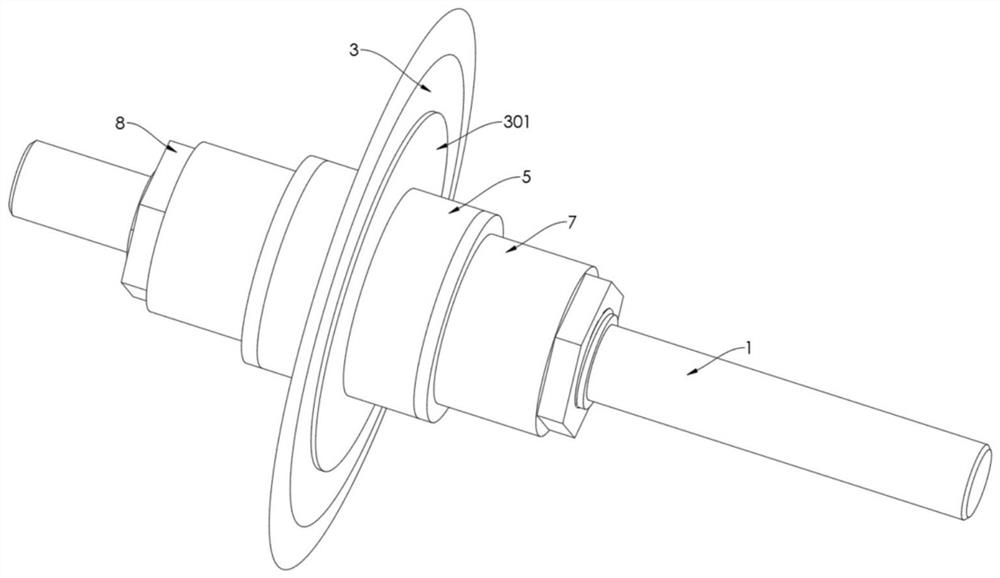
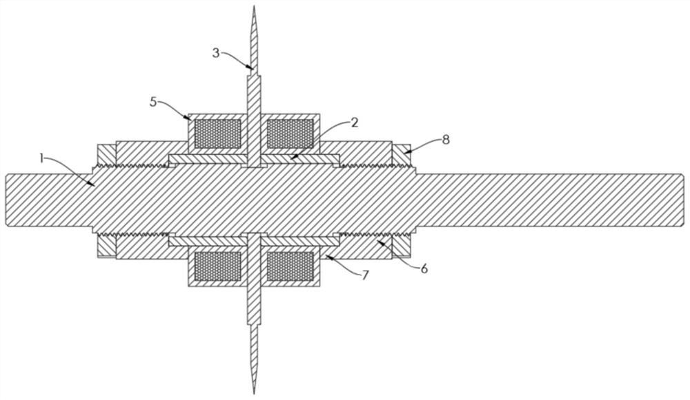
[0037] The blade installation shaft 1, the two sides of the blade installation shaft 1 are respectively integrally formed and outwardly provided with several fixed keys 101 arranged at equal angles;

[0038]A group of plug-in pipe fittings 2, the inner side walls of the plug-in pipe fittings 2 are respectively provided with corresponding fixing grooves 201 at positions corresponding to the fixing keys 101, and the group of plug-in pipe fittings 2 Respectively movably mounted on both sides of the blade installation shaft 1, the set of plug-in pipes 2 are respectively fixed and locked by corresponding fixed locking mechanisms, and the inner ends of the plug-in pipes 2 ar...


PUM


Abstract

The invention relates to a cutting mechanism for a pipe fitting cutting machine, which comprises a blade mounting shaft, and a plurality of fixing keys are respectively arranged on two sides of the blade mounting shaft; the inserting pipe fittings are movably mounted on the two sides of the blade mounting shaft in a key groove matching mode respectively, the inner ends of the inserting pipe fittings are integrally formed and outwards provided with corresponding limiting blocks respectively between every two adjacent fixing grooves, and the outer ends of the limiting blocks are arranged in an inclined plane shape; a blade mounting plate is arranged in the center of the cutting blade, a mounting hole is formed in the center of the blade mounting plate, corresponding receding grooves are formed in the positions, corresponding to the fixing keys, of the mounting hole respectively, and the two sides of each receding groove are arranged to be in an inclined plane shape matched with the corresponding limiting block; the set of inserting pipe fittings are fixedly connected to the two sides of the cutting blade in an abutting mode, and the limiting blocks abut against the inclined faces on the two sides of the receding groove respectively. The integral assembly stability is sufficient, and the notch precision of the pipe fitting can be effectively and greatly improved.

Description

technical field [0001] The invention relates to a cutting mechanism for a pipe fitting cutting machine, which is mainly used for cutting pipe fittings. Background technique [0002] Pipe cutting machine, as the name suggests, is a device for cutting pipes, and the cutting mechanism is the most important part of the pipe cutting machine. The existing cutting mechanism for the pipe cutting machine mainly includes a cutter shaft driven by a driving motor, and then the cutting blade is fixedly assembled on the cutter shaft through a corresponding blade locking and positioning mechanism. [0003] The existing blade locking and positioning mechanism generally includes a side stop fixed on one side of the cutter shaft, and then a locking part is detachably installed on the other side of the cutter shaft. During the assembly process: first assemble the cutting blade to the side stop Then lock the locking piece in place to realize the fixing of the cutting blade. By setting the corr...

Claims


Application Information

Patent Timeline
Patent Type & Authority Applications(China)
IPC IPC(8): B23Q3/12B23Q11/00
CPCB23Q3/12B23Q11/0032
Inventor 施文阳陈凯戎
Owner 福建纳川管业科技有限责任公司
Why Eureka
Try Eureka