Rapid cooling device for injection molding product processing

A technology for rapid cooling and injection molding products, used in transportation and packaging, separation methods, and dispersed particle separation, which can solve problems such as waste and multiple water resources.

Pending Publication Date: 2022-04-29
厦门诚汇达工贸有限公司
View PDF1 Cites 2 Cited by
  • Summary
  • Abstract
  • Description
  • Claims
  • Application Information

AI Technical Summary

Problems solved by technology

[0005] In order to overcome the disadvantage that the existing rapid cooling devices for processing injection molding products generally waste more water resources, the purpose of the present invention is to provide a rapid cooling device for processing injection molding products that saves water resources

Method used


Image

  • Rapid cooling device for injection molding product processing
  • Rapid cooling device for injection molding product processing
  • Rapid cooling device for injection molding product processing

Examples


Embodiment 1

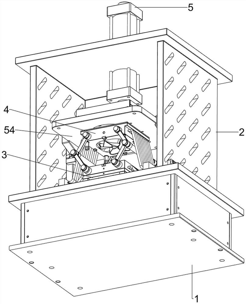
[0039] A rapid cooling device for processing injection molded products, refer to Figure 1-Figure 8 , including a base 1, a fixed frame 2, a bottom mold 3, a top mold 4, a lifting mechanism 5 and a cooling mechanism 6, the top of the base 1 is welded with a fixed frame 2, the top of the base 1 is provided with a bottom mold 3 in the middle, and the bottom mold 3 Located inside the fixed frame 2, the upper part of the fixed frame 2 is provided with a lifting mechanism 5, and the lifting mechanism 5 is provided with a top mold 4. The top mold 4 is located directly above the bottom mold 3, and the top mold 4 can be in contact with the bottom mold 3 when moving downward. together, so that the raw material can be shaped, and the base 1 is provided with a cooling mechanism 6 inside.

[0040] refer to figure 1 , figure 2 , Figure 4 and Figure 5, the lifting mechanism 5 includes a hydraulic cylinder 51, the first slide rail 52, a sliding frame 53 and a fixed plate 54, the upper...

Embodiment 2

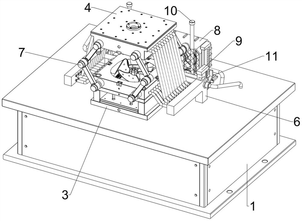
[0044] On the basis of embodiment 1, refer to image 3 and Figure 9 , also includes a stretching mechanism 7, and the stretching mechanism 7 includes a first connecting block 71, a second connecting block 72, a connecting rod 73 and a first ejector rod 74, and the front and rear sides of the top mold 4 are welded symmetrically to the left and right. A connection block 71, the front and rear sides of the bottom mold 3 are welded symmetrically with the second connection block 72, the first connection block 71 and the second connection block 72 are all rotatably provided with connecting rods 73, and the four corresponding connecting rods in the front and back The inner sides of the rods 73 are all rotatably provided with first push rods 74, and the first push rods 74 are all in contact with the adjacent third conduits 64. When the first push rods 74 move outward, the third conduits 64 can be pushed away. , to prevent the third conduit 64 from entering between the top mold 4 and...


PUM


Abstract

The invention relates to a rapid cooling device, in particular to a rapid cooling device for injection molding product machining. The invention aims to provide the quick cooling device for processing the injection molding product, which saves water resources. The rapid cooling device comprises a base, a fixing frame, a bottom mold, a top mold, a lifting mechanism and the like, the fixing frame is arranged at the top of the base, the bottom mold is arranged in the middle of the top of the base and located on the inner side of the fixing frame, the lifting mechanism is arranged on the upper portion of the fixing frame, and the top mold is arranged on the lifting mechanism. The hydraulic cylinder serves as driving force to drive the top mold to move downwards to make contact with the bottom mold, then raw materials are manually injected between the top mold and the bottom mold, the water pump serves as driving force, water can be conveyed into the top mold and the bottom mold, the raw materials are cooled, and then the water can flow back into the material storage box; and the purpose of water recycling is achieved.

Description

technical field [0001] The invention relates to a rapid cooling device, in particular to a rapid cooling device for processing injection molded products. Background technique [0002] In the production process of injection molded products, they are usually injected into the mold after heating and plasticizing, and then wait for natural air drying, which takes a long time. [0003] Patent application CN213500660U, with a publication date of 20210622, discloses a rapid cooling device for processing injection molded products, including a cooling box. One side of the cooling box is fixedly connected with a motor storage box and a cooling machine storage box from top to bottom. The inside of the cooling machine placement box is fixedly connected with a cooling machine, and the output port of the cooling machine is fixedly connected with a water injection connecting pipe, and one side of the water injection connecting pipe is fixedly connected with two water delivery pipes, and th...

Claims


Application Information

Patent Timeline
IPC IPC(8): B29C45/26B29C45/67B29C45/73B29C45/17B01D46/10B01D46/681
CPCB29C45/2602B29C45/67B29C45/7312B29C45/1753B01D46/10
Inventor 谢冬英陈燕明
Owner 厦门诚汇达工贸有限公司
Why Eureka
Try Eureka