Automatic filling production line

An automatic filling and production line technology, applied in packaging, packaging bottles, packaging machines, etc., can solve the problems of low automation of filling production lines, offset and detachment of packaging boxes, etc., to improve automation efficiency, improve transportation efficiency, and facilitate use. Effect

Pending Publication Date: 2022-04-29
罗柱林 +2
0 Cites 0 Cited by

AI-Extracted Technical Summary

Problems solved by technology

[0003] An automatic filling production line proposed by the present invention solves the problem that the packing box is easy to deviate from the predetermined tr...

Abstract

The invention discloses an automatic filling production line, relates to the technical field of filling production, and aims to solve the problems that an existing packaging box is easy to deviate and break away from a preset track in the conveying process, the automation degree of the filling production line is low, and liquid needs to be manually filled into a bottle body. A bottle conveying mechanism is arranged on the base, a filling mechanism is arranged on one side of the bottle conveying mechanism, the filling mechanism is used for filling liquid, a labeling mechanism is arranged on the side, away from the bottle conveying mechanism, of the filling mechanism, a boxing mechanism is arranged on one side of the labeling mechanism, and a box opening mechanism is arranged on one side of the boxing mechanism. According to the automatic filling production line, the limiting mechanism can be adjusted according to the size of the packaging box, so that the packaging box is not prone to deviation on the conveying belt, the conveying efficiency is improved, meanwhile, the filling bottle does not need to be manually held by hand for filling, the automation efficiency of the filling production line is improved, and use is convenient.

Application Domain

Threaded caps applicationConveyors +7

Technology Topic

Labelling machineProcess engineering +5

Image

  • Automatic filling production line
  • Automatic filling production line
  • Automatic filling production line

Examples

  • Experimental program(1)

Example Embodiment

[0022] The technical solutions in the embodiments of the present invention will be clearly and completely described below with reference to the accompanying drawings in the embodiments of the present invention. Obviously, the described embodiments are only a part of the embodiments of the present invention, rather than all the embodiments.
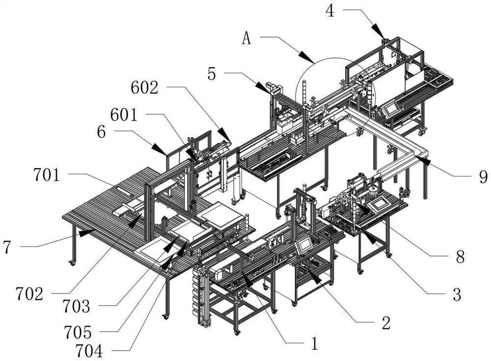
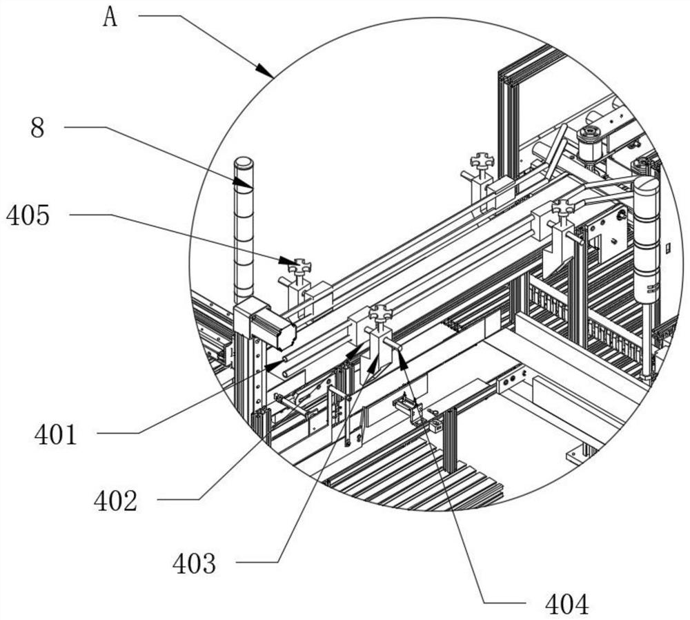
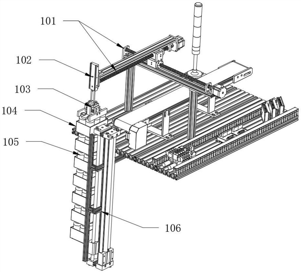
[0023] refer to Figure 1-Figure 4 As shown, an automatic filling production line includes a bottle feeding mechanism 1, a filling mechanism 2 is provided on one side of the bottle feeding mechanism 1, and the filling mechanism 2 is used for filling liquid, and the filling mechanism 2. A labeling mechanism 3 is arranged on the side away from the bottle feeding mechanism 1, a packing mechanism 5 is arranged on one side of the labeling mechanism 3, and an unpacking mechanism 4 is arranged on one side of the packing mechanism 5. The unpacking mechanism 4 is used for the unfolding of the box body, the packing mechanism 5 is provided with a packing mechanism 6 on the side away from the packing mechanism 4, and the side of the packing mechanism 6 away from the packing mechanism 5 is provided with palletizing. Institution 7;
[0024] The unpacking mechanism 4 includes a limit rod 401, a fixed block 402, an engagement block 403, a sliding rod 404 and a threaded rod 405. The circumferential side wall of the limit rod 401 is connected with the fixed block 402. The limit rod 401 is symmetrically arranged with the central axis of the fixed block 402, one end of the fixed block 402 away from the limit rod 401 is connected with the sliding rod 404, and one end of the sliding rod 404 away from the fixed block 402 extends to the outside through the connecting block 403 .
[0025] like Figure 1-Figure 3 As shown, the threaded rod 405 is located at the top of the connecting block 403, and the bottom end of the threaded rod 405 passes through the connecting block 403 to clamp and fix the sliding rod 404. The bottle feeding mechanism 1 includes an adjustment sliding table 101, The first telescopic cylinder 102, the second telescopic cylinder 103, the placing box 104, the filling bottle 105 and the conveying slide table 106, the conveying slide table 106 is located on one side of the placing box 104, and the filling bottle 105 is located in the placing box Inside 104 , one end of the adjusting slide 101 is connected with the first telescopic cylinder 102 , and the end of the piston rod of the first telescopic cylinder 102 is connected with the second telescopic cylinder 103 , which is driven by activating the third telescopic cylinder 201 The filling head 203 moves to the top of the filling bottle 105, and then the fourth telescopic cylinder 202 is activated, and the fourth telescopic cylinder 202 drives the filling head 203 to extend into the filling bottle 105 to fill the liquid.
[0026] like figure 1 and Figure 4 As shown, the filling mechanism 2 includes a third telescopic cylinder 201, a fourth telescopic cylinder 202 and a filling head 203. The end of the piston rod of the third telescopic cylinder 201 is connected to the fourth telescopic cylinder 202, and the The end of the piston rod of the fourth telescopic cylinder 202 is connected with the filling head 203, and the stacking mechanism 7 includes a first electric telescopic rod 701, a conveying plate 702, a second electric telescopic rod 703, a clamping plate 704 and a limiter Conveyor belt 705, the first electric telescopic rod 701 is located on one side of the conveying plate 702, the conveying plate 702 is located between the first electric telescopic rod 701 and the clamping plate 704, the piston of the second electric telescopic rod 703 The end of the rod is connected with the clamping plate 704, the limit conveyor belt 705 is located at the bottom end of the clamping plate 704, one end of the U-shaped conveyor belt 9 is connected with the labeling mechanism 3, the U-shaped conveyor belt 9. One end away from the labeling mechanism 3 is connected to the packing mechanism 5. The bottle feeding mechanism 1, the filling mechanism 2, the labeling mechanism 3, the unpacking mechanism 4, the packing mechanism 5 and the palletizing mechanism 7 are all set There is an indicator light 8, and the sealing mechanism 6 includes an adhesive block 601 and a folding block 602. Both the adhesive block 601 and the folding block 602 are located inside the sealing mechanism 6, and the adhesive block 601 is located in the folding block. On one side of 602 , the four-corner cover of the packaging box is folded by the folding plate 602 on the sealing mechanism 6 , and then the folded packaging box is glued and sealed by the glue sticking block 601 .
[0027] Working principle: When the device is in use, first start the conveying slide table 106 in the bottle feeding mechanism 1 to transport the filling bottles 105 inside the placing box 104 upward, and then start the adjusting slide table 101 to move the fixed plate on the second telescopic cylinder 103 Align the filling bottle 105, and then activate the second telescopic cylinder 103 to drive the fixed plate to clamp the filling bottle 105 to the conveyor belt in the bottle feeding mechanism 1, so as to transport the filling bottle 105 to the filling mechanism 2 At the same time, the third telescopic cylinder 201 is activated to drive the filling head 203 to move to the top of the filling bottle 105, and then the fourth telescopic cylinder 202 is activated to drive the filling head 203 into the filling bottle 105 through the fourth telescopic cylinder 202. Fill the liquid, and then the filling head 203 slowly moves upward to complete the filling, and then seals it by the capping machine on the filling mechanism 2. The bottle 105 is transported to the labeling mechanism 3, and then the filling bottle 105 is subjected to labeling processing. After the labeling is completed, the filling bottle 105 is transported to the packing mechanism 5 through the U-shaped conveyor belt 9, and the unpacking mechanism 4 is activated at the same time. The packing box is opened and transported to the packing mechanism 5, and then the filling bottle 105 is transported to the inside of the packing box through the suction cup on the packing mechanism 5, and then the filling bottle 105 is filled with the transport belt on the packing mechanism 5 The folded packaging box is transported to the inside of the sealing mechanism 6, and then the four-corner cover of the packaging box is bent through the folding plate 602 on the sealing mechanism 6, and then the folded packaging box is glued and sealed by the glue block 601. Then the packing box is transported to the palletizing mechanism 7, at this time, the first electric telescopic rod 701 is activated to move the packing box to the conveying plate 702, and at the same time, the conveying plate 702 is activated to transport the packing box on the conveying plate 702 to the clamping plate At 704, the second electric telescopic rod 703 is then activated to drive the clamping plate 704 to clamp the packaging box, then the conveying plate 702 returns to the first electric telescopic rod 701, and finally, the clamping plate 704 is released, and the packaging box falls directly to the limit conveyor belt 705.
[0028]The above description is only a preferred embodiment of the present invention, but the protection scope of the present invention is not limited to this. The equivalent replacement or change of the inventive concept thereof shall be included within the protection scope of the present invention.

PUM

no PUM

Description & Claims & Application Information

We can also present the details of the Description, Claims and Application information to help users get a comprehensive understanding of the technical details of the patent, such as background art, summary of invention, brief description of drawings, description of embodiments, and other original content. On the other hand, users can also determine the specific scope of protection of the technology through the list of claims; as well as understand the changes in the life cycle of the technology with the presentation of the patent timeline. Login to view more.

Similar technology patents

Classification and recommendation of technical efficacy words

  • Improve delivery efficiency
  • High automation efficiency

Commodity ex-warehouse method

Owner:BEIJING JINGDONG ZHENSHI INFORMATION TECH CO LTD

Meal delivery robot applied to intelligent cafeteria and intelligent cafeteria

PendingCN107030710ASave delivery timeImprove delivery efficiencyData processing applicationsTable equipmentsRobotyMeal preparation
Owner:ZHONGSHAN AOSI FINE MACHINERY TECH

Database deployment method and device

ActiveCN104717233AImprove delivery efficiencyFile access structuresData switching networksDatabase fileDatabase application
Owner:CHINA TELECOM CORP LTD

Automatic detection equipment

InactiveCN105598043AHigh automation efficiencyReduce worker workloadSortingEngineeringAutomatic test equipment
Owner:SUZHOU AMITY ELECTRONICS & PLASTICS

Tableware-pattern-based pricing method of dish automatic identification system

InactiveCN106056487AHigh automation efficiencyLow costData processing applicationsCo-operative working arrangementsMachine vision systemAutomation
Owner:HANGZHOU HUICUI INTELLIGENT TECH CO LTD

Method for automatic classification of regression testing case

InactiveCN107102939AHigh automation efficiencySoftware testing/debuggingCase baseSoftware changes
Owner:CHINA UNIV OF MINING & TECH

Cold metal transition welding repairing method for wear or breakage of jet nozzle of universal pitot tube pump

InactiveCN107470851AMeet the machining accuracyHigh automation efficiencyNon-electric welding apparatusCentrifugal pumpPetrochemical
Owner:浙江翰德圣智能再制造技术有限公司
Why Eureka
Try Eureka