
Combined conical section composite shell structure

A shell structure and combined technology, applied in the direction of machines/engines, rocket engine devices, jet propulsion devices, etc., can solve the problems of large negative mass of the structure, low space utilization rate of the transition section between stages, and low space utilization rate. Achieve the effect of improving space utilization, reducing negative mass and increasing loading capacity

Active Publication Date: 2022-04-29
SHANGHAI XINLI POWER EQUIP RES INST
View PDF4 Cites 0 Cited by
  • Summary
  • Abstract
  • Description
  • Claims
  • Application Information

AI Technical Summary

Problems solved by technology

[0003] The technical problem of the present invention is to overcome the deficiencies of the prior art and provide a combined cone section composite shell structure, which solves the problem of low space utilization rate of the traditional non-cone section composite shell structure and low space utilization rate of the transition section between stages. The overall negative quality of the structure is large, etc.

Method used


Image

  • Combined conical section composite shell structure
  • Combined conical section composite shell structure
  • Combined conical section composite shell structure

Examples


Embodiment Construction

[0043] In order to make the object, technical solution and advantages of the present invention clearer, the embodiments disclosed in the present invention will be further described in detail below in conjunction with the accompanying drawings.

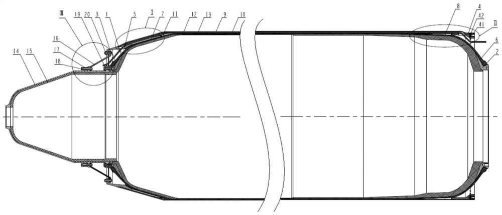
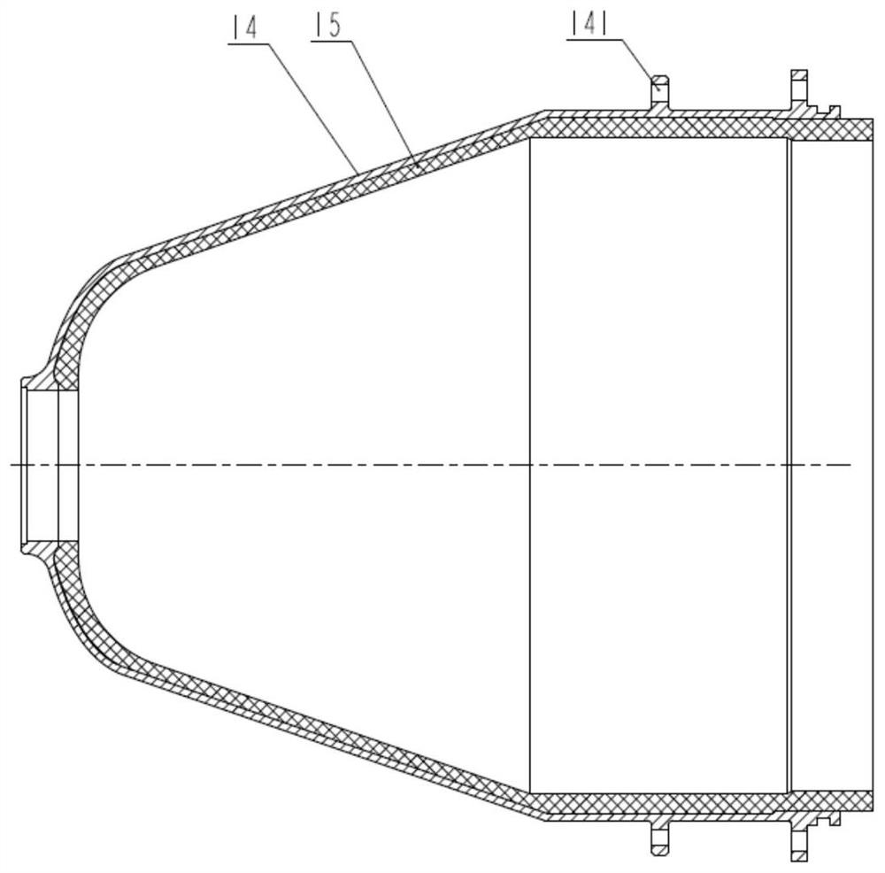
[0044] In this embodiment, the combined conical section composite shell structure includes: a conical composite shell, a front cabin and a cabin section connection structure. Wherein, the front cabin is installed on the head of the tapered composite shell through the cabin connection structure.

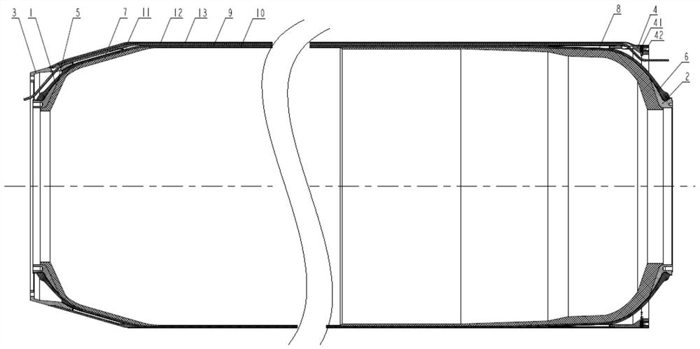
[0045] In this example, if figure 1 , 2 And 4, the tapered composite shell can specifically include: front joint 1, rear joint 2, front skirt 3, rear skirt 4, front joint protection layer 5, rear joint protection layer 6, front skirt protection layer 7, rear skirt protection layer 8. Composite housing heat insulation layer 9 , winding layer 10 , skirt fixing layer 11 , cable 12 and cable fixing layer 13 .

[0046] The wrapping layer 10 is w...


PUM


Abstract

The invention discloses a combined conical section composite shell structure which comprises a conical composite shell, a front cabin and a cabin section connecting structure. The front cabin is installed on the head of the composite shell with the cone through a cabin section connecting structure. The space utilization rate of the composite shell is greatly improved through the design of the composite shell conical section structure, effective utilization of the charging space of the boosting engine with the conical section is achieved in combination with the forecabin structure, meanwhile, the negative mass of the shell is greatly reduced, the impact mass ratio of the engine is increased, and the problems that a traditional non-conical-section composite shell structure is low in space utilization rate and low in cost are solved. The problems that the docking space of the cabin sections cannot be utilized, and the overall passive mass of the structure is large are solved, meanwhile, the cabin section connecting structure is used for achieving sharing of the gravity of the forecabin in the vertical state of the rocket and releasing of axial stress in the internal pressure working state, and side deformation discordance between the forecabin and the composite shell is avoided.

Description

technical field [0001] The invention belongs to the technical field of solid rocket motor composite shell design, and in particular relates to a combined cone-section composite shell structure. Background technique [0002] In order to improve the performance of the rocket, the conventional multi-stage rocket structure usually uses a solid rocket motor with a composite shell as the combustion chamber as the booster stage. There is usually a large connection space between the booster engine and the main stage engine for the interstage Therefore, there is a lot of unused space in the transition section between the engine stages. While increasing the overall negative mass of the rocket, the utilization rate of the limited space is also greatly reduced, thus limiting the further improvement of the overall structural performance of the rocket. Contents of the invention [0003] The technical problem of the present invention is to overcome the deficiencies of the prior art and p...

Claims


Application Information

Patent Timeline
Patent Type & Authority Applications(China)
IPC IPC(8): F02K9/34
CPCF02K9/34F02K9/346F02K9/343Y02T50/40
Inventor 林天一郑庆杨明童悦薛潇潇何鹏江真王林祥李德华金书明
Owner SHANGHAI XINLI POWER EQUIP RES INST
Learn More