
Gas sensing dynamic testing device and gas sensing testing method

A technology of gas sensing and dynamic testing, which is applied in the direction of measuring devices, electrical components, and material analysis through electromagnetic means, and can solve the problems affecting the accuracy of material intrinsic testing, electromagnetic signal interference, and affecting the baseline and test data of test circuits Accuracy and other issues to achieve the effect of improving electrical shielding performance, ensuring accuracy and effectiveness

Pending Publication Date: 2022-04-29
FUJIAN INST OF RES ON THE STRUCTURE OF MATTER CHINESE ACAD OF SCI
View PDF6 Cites 0 Cited by
  • Summary
  • Abstract
  • Description
  • Claims
  • Application Information

AI Technical Summary

Problems solved by technology

However, the electromagnetic signal interference problem exists in the glass chamber and the plastic chamber, which seriously affects the baseline of the test circuit and the accuracy of the test data, which in turn will affect the sensitivity and selectivity of the gas obtained by calculating the current or resistance data after processing. adverse effects on performance
The stainless steel chamber introduced by the electrical connector can effectively solve the problem of electrical signal shielding. However, most chambers currently have the problem of large test volume. When the detection gas fills the chamber and diffuses to the surface of the sensing element, it takes a certain amount of time to make the material The corresponding speed deviates from the real, which indirectly affects the test accuracy of the material intrinsic

Method used


Image

  • Gas sensing dynamic testing device and gas sensing testing method
  • Gas sensing dynamic testing device and gas sensing testing method

Examples


Embodiment 1

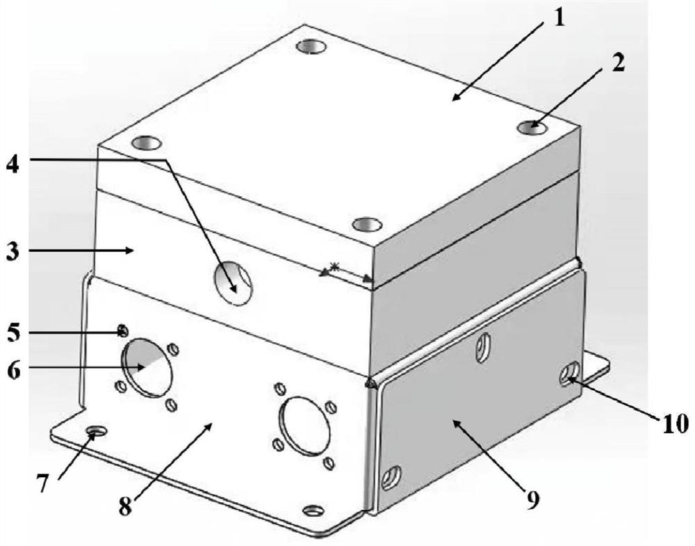
[0035] The present embodiment provides a gas sensing dynamic testing device, comprising a stainless steel upper cavity 3 and a stainless steel lower cavity, the stainless steel lower cavity is composed of a stainless steel plate 8 and a stainless steel plate 9 and the lower end surface of the stainless steel upper cavity 3; the stainless steel upper cavity The cavity 3 is provided with a stainless steel cover plate 1, and the stainless steel cover plate 1 and the stainless steel upper cavity 3 are sealed and connected by a sealing ring;

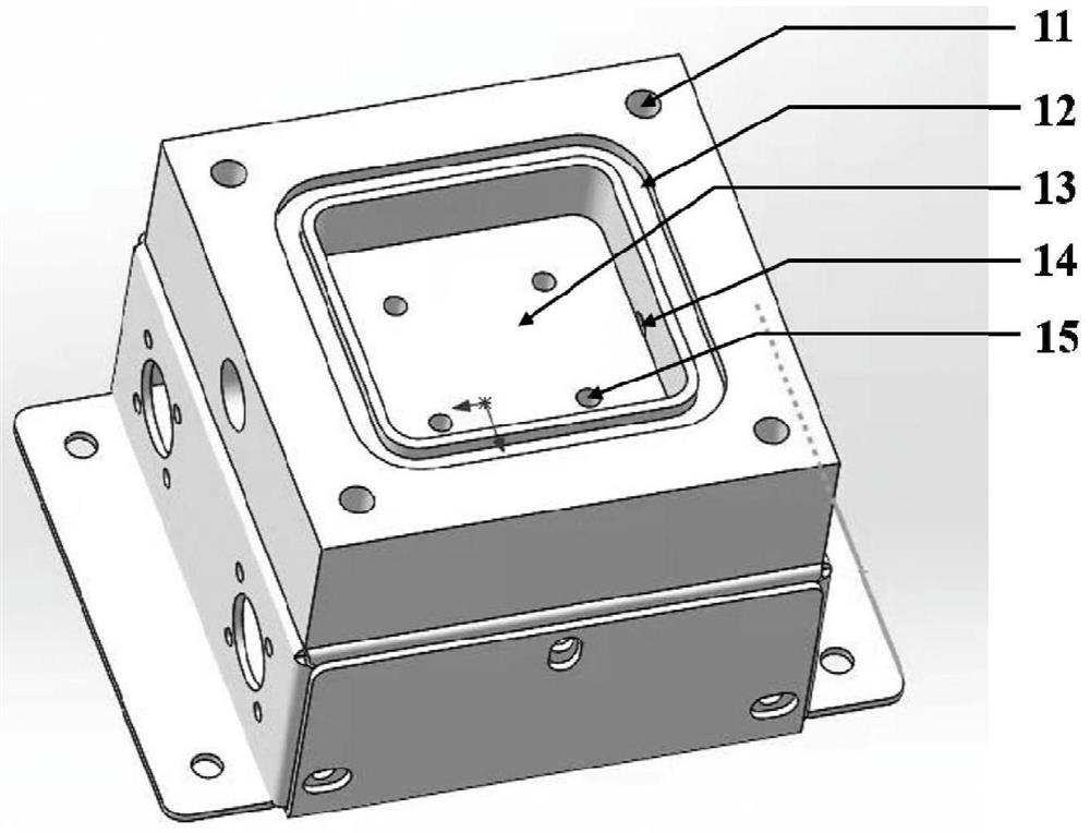
[0036] The side wall of the stainless steel upper cavity 3 is provided with an inlet hole 4 and an air outlet hole 14; the lower end surface is provided with 4 evenly distributed through holes 15;

[0037] The test module is fixed on the lower cavity through the BNC slot 6, the silver-plated copper wire passes through the through hole 15, one end is electrically connected with the two samples to be tested in the stainless steel upper cavity, a...

Embodiment 2

[0039] This embodiment provides a specific gas sensing dynamic testing device, such as figure 1 , figure 2 As shown, from top to bottom, the stainless steel cover plate 1 is connected to the stainless steel cavity 3 through the threaded hole 2 by screws with guide holes; a closed stainless steel cavity is constructed. A sealing ring is placed in the sealing groove 12 in the stainless steel cavity 3 to increase the sealing performance. Air intake holes 4 are opened on both sides of the cavity, and gas enters and exits through internal air outlet holes 14 .

[0040] In the lower part of the stainless steel sealed cavity, the stainless steel plate is fixed by threads on four sides to form an electromagnetic shielding box. The BNC electrical connectors are fixed on the steel plates on both sides through the electrode holes 15 by screws on both sides.

[0041] The BNC electrode head is connected with the electrodes in the electrode holes 15 through metal wires to form a test pa...

Embodiment 3

[0047] Before testing the sample, put the sample to be tested into the middle of the test chamber, connect it with the test electrode through the gold wire, then fix the stainless steel cover plate on the test chamber through threaded screws, and tighten the screws to make the upper stainless steel plate and stainless steel The cavity forms a closed system.

[0048] During the test, the gas to be tested is introduced from the air inlet, so that the gas enters the test chamber at a fixed flow rate and flows out from the air outlet. At this time, use the coaxial line through the BNC connector and the source meter to connect, record the input electrical signal and output electrical signal, and complete the test.

[0049] At a flow rate of 200 sccm, the gas enters and fills the entire chamber in less than 1 second, maximizing the contact between the gas and the sample, and effectively improving the test efficiency.


PUM


Abstract

The invention discloses a gas sensing dynamic testing device and a gas sensing testing method. The gas sensing dynamic testing device comprises a cavity and an electric signal transmission unit, the cavity is a stainless steel cavity and is divided into an upper cavity and a lower cavity, and the lower end face of the upper cavity is the upper end face of the lower cavity; the upper cavity is provided with a cover body in sealed connection; the electric signal transmission unit comprises a test module; the electric signal transmission unit is connected with the lower cavity; an air inlet and an air outlet are formed in the cavity side wall of the upper cavity; a through hole for mounting an electrode is formed in the lower end surface of the upper cavity; a sensing element to be detected is arranged in the cavity; and the test module is electrically communicated with the sensing element to be tested. While the electrical shielding performance of the current gas sensing test cavity is improved, the gas to be tested can instantly enter the cavity, so that the accuracy and effectiveness of test data are ensured.

Description

technical field [0001] The application relates to a gas sensing dynamic testing device and a gas sensing testing method, belonging to the field of electronic information sensors. Background technique [0002] Gas sensing test chamber is an important component of laboratory gas sensing sample testing. Its air tightness, electromagnetic signal shielding and gas flow are directly related to the accuracy, reliability and rigor of gas sensing test data. [0003] At present, the gas test chamber in the laboratory mostly adopts a glass / quartz tube closed by stainless steel flanges at both ends, a square plastic chamber containing a test circuit board, and a cylindrical polytetrafluoroethylene chamber introduced by an electrical connector. However, the electromagnetic signal interference problem exists in the glass chamber and the plastic chamber, which seriously affects the baseline of the test circuit and the accuracy of the test data, which in turn will affect the sensitivity and...

Claims


Application Information

Patent Timeline
Patent Type & Authority Applications(China)
IPC IPC(8): G01N27/00G01N27/04H05K9/00
CPCG01N27/00G01N27/04H05K9/0007
Inventor 付志华徐刚
Owner FUJIAN INST OF RES ON THE STRUCTURE OF MATTER CHINESE ACAD OF SCI
Learn More