High-power direct current engine comprising a collector and carbon brushes for a racing car serving as prototype

Inactive Publication Date: 2005-02-10
TEAM ORION EURO
View PDF21 Cites 11 Cited by
  • Summary
  • Abstract
  • Description
  • Claims
  • Application Information

AI Technical Summary

Benefits of technology

[0022] The invention is a high-power DC motor with a commutator and brushes for model racing vehicles, in particular model racing cars, which avoids the disadvantages of known DC motors and, in particular, cou

Problems solved by technology

When sliding bearings are used, the gap increases as the sliding bearings wear.
The electrical contact is made with a time delay, and the power of the motor falls.
The commutator segments 20 are damaged, and the quality of the current transmission suffers and falls.
This adversely affects the life of the motor, and reduces its power.
The sparks also cause radio interference and can interfere with remote control receiving systems, or even make them unusable, when motors such as these are operated in the vicinity of radio receivers.
This damping (braking) thus delays the time at which contact is next made between the brushes and the commutator segments.
No improvements can be achieved in this way.
If this electrical resistance could be reduced, then the motor would produce more power The known solutions for damping and braking the backward and forward movement of the brushes do not allow any improvements whatsoever with regard to reducing the magnitude of the resistance.
The use of the edges of the brushes for guidance results in a greatly reduced contact area between the brushes and the brush boxes, which on the one hand prevents effective friction damping of the brush movement, and on the other hand makes it more difficult to supply current to the brush tip via the brush box.
This admittedly results in increased frict

Method used


Image

  • High-power direct current engine comprising a collector and carbon brushes for a racing car serving as prototype
  • High-power direct current engine comprising a collector and carbon brushes for a racing car serving as prototype
  • High-power direct current engine comprising a collector and carbon brushes for a racing car serving as prototype

Examples


Example

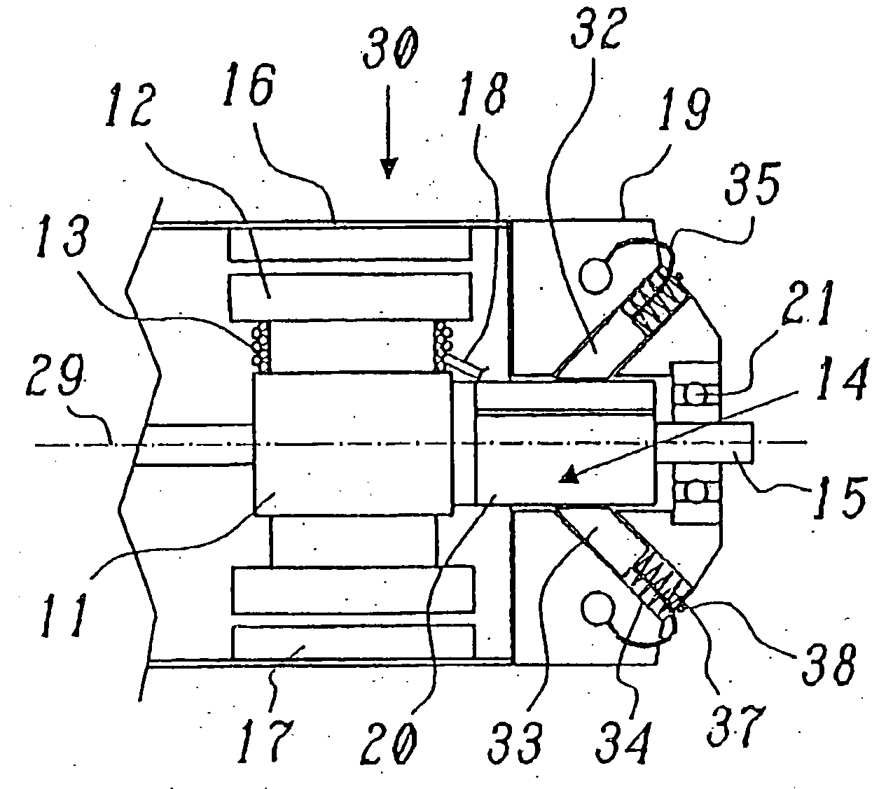
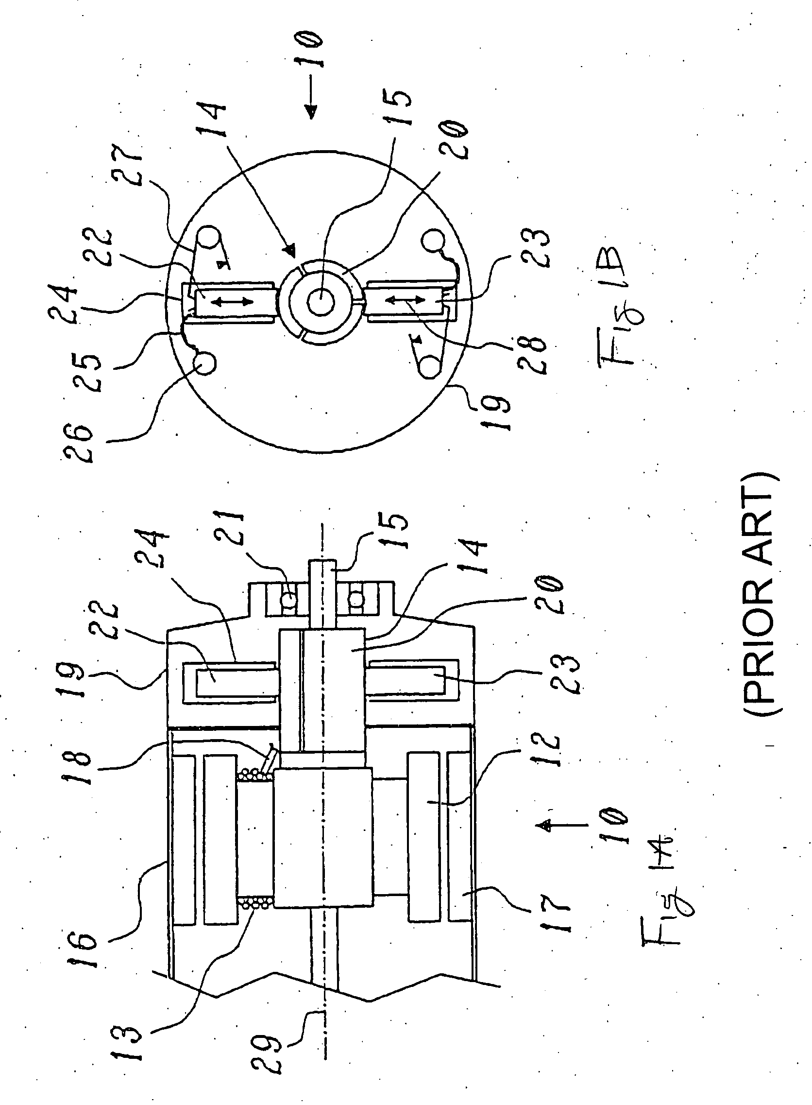
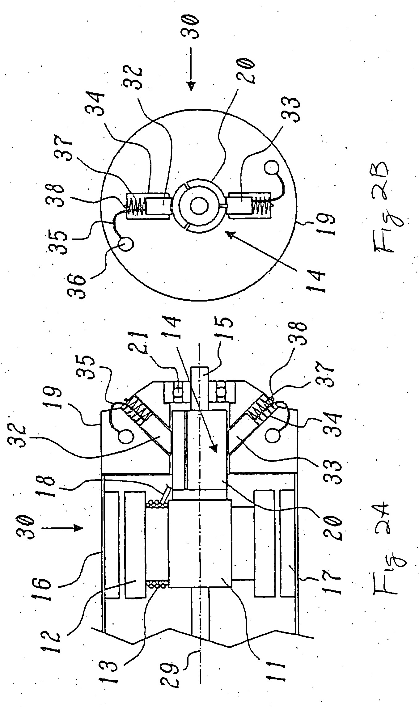
[0050]FIGS. 2A and 2B show a DC motor according to a first embodiment of the invention, with FIG. 2A showing a longitudinal section through the motor and FIG. 2B showing a plan view in the direction of the axis. The same parts are in this case provided with the same reference symbols as in FIGS. 1A and 1B. FIG. 3 shows an enlarged detailed view of one of the brushes from FIG. 2A.

[0051] The DC motor illustrated in FIGS. 2A and 2B differs from the known motor shown in FIGS. 1A and 1B by the arrangement of the brushes 32, 33 relative to the (unchanged) commutator 14. The brushes 32, 33 are oriented with their associated brush boxes 34 obliquely outwards, so that their movement direction 39 (double-headed arrow in FIG. 3), which is predetermined by the brush boxes 34 and is the same as the direction of the force vector C in the force parallelogram shown in FIG. 3, includes an angle α (alpha) with the radial direction with respect to the axis 29, which is at the same time the direction ...

Example

[0054]FIGS. 4A and 4B show a DC motor 40 according to a second embodiment of the invention, with FIG. 4A showing a longitudinal section through the motor and FIG. 4B showing a plan view in the axial direction. The same parts are in this case provided with the same reference symbols as in FIGS. 1A and 1B. FIG. 5 shows an enlarged detailed view of one of the brushes from FIG. 4B.

[0055] As can be seen from FIG. 4B, the brush boxes 44 for the brushes 42, 43 no longer lie on a common plane which passes through the axis 29, but on a common plane which is at right angles to the axis 29 (see FIG. 4A). The oblique position of the movement direction 41 (FIG. 5) relative to the radial direction (the dashed line in the force parallelogram in FIG. 5) is in this case achieved by the two brushes 42, 43 being arranged laterally offset parallel in the opposite direction from the position shown in FIG. 1B. This also results in a tilt angle α, which leads to the radial force A being resolved into two...


PUM


Abstract

A DC motor includes a rotor which is mounted in a housing so that it can rotate about an axis. The rotor includes at least one winding to which direct current is applied from the outside in alternating directions via a commutator, which is arranged on the rotor. Brushes are seated on the commutator and are mounted whereupon they can move relative to the commutator while being pushed by spring pressure onto the commutator.

Description

BACKGROUND OF THE INVENTION [0001] 1. Technical Field [0002] The present invention relates to the field of DC motor technology. It relates in particular to a high-power DC motor, especially for model racing vehicles. [0003] 2. Prior Art [0004] Small, extremely high-power DC motors which rotate at a high speed are used nowadays for driving battery-powered model racing cars, model boats or model aircraft. Examples of such high-power DC motors for model racing cars are the RC2140 or RC2141 types from the American company Trinity Products, Inc. Edison, N.J. (USA), or the “Chrome Touring” series of motors from the Swiss company Team Orion Europe SA, 1233 Bernex, Switzerland. FIG. 1 shows an example of the design of such DC motors from the prior art in simplified form and in the form of a detail, with the figure element 1A showing a longitudinal section through the motor and the figure element 1B showing a plan view in the axial direction of the motor head. The DC motor 10 shown in FIG. 1...

Claims


Application Information

Patent Timeline
IPC IPC(8): A63H29/22H01R39/38H01R39/41H02K5/14H02K5/173H02K5/18H02K13/10H02K23/66
CPCA63H29/22H01R39/385H01R39/41H02K23/66H02K5/1732H02K5/18H02K13/10H02K5/148H02K9/28
Inventor NEIDHART, PHILIPPE
Owner TEAM ORION EURO
Why Eureka
Try Eureka