High-precision self-calibration synchronous triggering device and method

A synchronous trigger and self-calibration technology, which is applied to measuring devices, digital variable/waveform displays, instruments, etc., can solve the problems of difficult calibration, low precision, and slow leading edge, and achieve the effects of convenient calibration, high precision, and small transmission delay

Pending Publication Date: 2022-04-29
NORTHWEST INST OF NUCLEAR TECH
View PDF0 Cites 2 Cited by
  • Summary
  • Abstract
  • Description
  • Claims
  • Application Information

AI Technical Summary

Problems solved by technology

[0006] The purpose of the present invention is to solve the technical problems of low precision, slow leading edge and difficult calibration in the synchronous trigger device for large-scale data acquisition in the existing large-scale pulse power device, and provide a high-precision self-calibration synchronous trigger device and method to realize large-scale The synchronous trigger device of pulse power has high precision, fast leading edge and self-calibration function, which meets the batch data acquisition requirements of large pulse power devices

Method used


Image

  • High-precision self-calibration synchronous triggering device and method
  • High-precision self-calibration synchronous triggering device and method
  • High-precision self-calibration synchronous triggering device and method

Examples


Embodiment Construction

[0050] The technical solutions of the present invention will be clearly and completely described below in conjunction with the accompanying drawings. Apparently, the described embodiments are some of the embodiments of the present invention, but not all of them. Based on the embodiments of the present invention, all other embodiments obtained by persons of ordinary skill in the art without making creative efforts belong to the protection scope of the present invention.

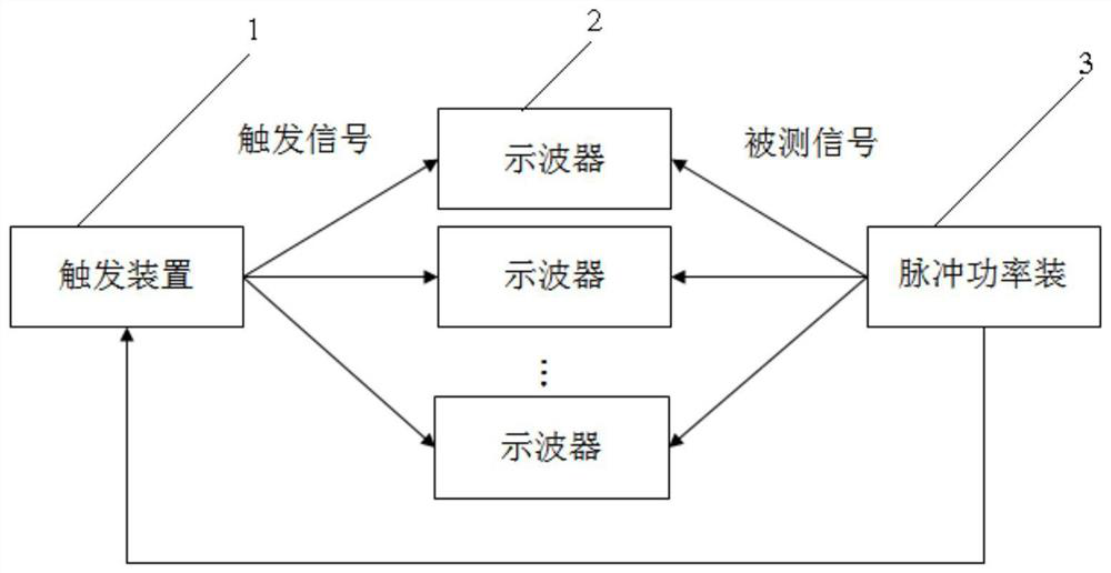
[0051] see figure 1 , in the large-scale pulse power device 3 batch pulse data acquisition system, the oscilloscope 2 and the synchronous trigger device 1 are the core parts of the batch pulse data acquisition system, and the output pulse signal of the large-scale pulse power device 3 itself or the experimental object passes through the coaxial cable The analog signal input channel of the oscilloscope 2 and the input end of the synchronous trigger device 1 are transmitted, and the external trigger channel of t...


PUM


Abstract

The invention relates to a synchronous triggering device, in particular to a high-precision self-calibration synchronous triggering device and a high-precision self-calibration synchronous triggering method, and solves the technical problems that a synchronous triggering device for large-scale data acquisition in an existing large-scale pulse power device is low in precision, slow in leading edge and difficult to calibrate. The high-precision self-calibration synchronous triggering device comprises a preprocessing circuit, a fan-out circuit, a reference channel, n calibration channels, a logic OR circuit, a calibration enabling circuit and a calibration signal circuit, wherein n is greater than or equal to 2; the output end of the preprocessing circuit is connected with the input end of the fan-out circuit; the reference channel and the n calibration channels are connected in parallel at the output end of the fan-out circuit; the reference channel comprises a reference time delay circuit and a reference driving circuit which are connected in sequence; each calibration channel comprises a calibration delay circuit, a calibration drive circuit, a comparison circuit and a delay drive circuit; the invention further provides a high-precision self-calibration synchronous triggering method based on the high-precision self-calibration synchronous triggering device.

Description

technical field [0001] The invention relates to a synchronous trigger device, in particular to a high-precision self-calibration synchronous trigger device and a realization method based on the high-precision self-calibration synchronous trigger device. Background technique [0002] With the rapid development of pulse power technology in recent years, pulse power devices show the characteristics of high power, large devices and multiple parallel operation; "Julong No. 1" developed by China Academy of Engineering Physics uses an oscilloscope to build a 300-channel data acquisition system ; When a large-scale oscilloscope system is used for data acquisition, all oscilloscopes must be triggered at the same time to ensure that all data have the same zero time. [0003] There are two ways to implement the existing synchronous trigger device. One is to use commercial devices to build. For example, Hermes III in the United States uses DG535+DG645+ power splitter to complete the tri...

Claims


Application Information

Patent Timeline
Patent Type & Authority Applications(China)
IPC IPC(8): G01R13/00G01R35/00
CPCG01R13/00G01R35/005
Inventor 周文渊呼义翔尹佳辉罗维熙张信军孙江张金海唐飞
Owner NORTHWEST INST OF NUCLEAR TECH
Why Eureka
Try Eureka