Withstand voltage test device and detection method for flexible connection copper bar for new energy automobile
A new energy vehicle, withstand voltage testing technology, applied in the direction of testing dielectric strength, measuring device casing, etc., can solve problems such as large differences, different test tooling requirements, prone to test blind spots, etc., to reduce losses and meet the withstand voltage test. requirements, the effect of reducing the switching time
- Summary
- Abstract
- Description
- Claims
- Application Information
AI Technical Summary
Problems solved by technology
Method used
Image
Examples
Embodiment 1
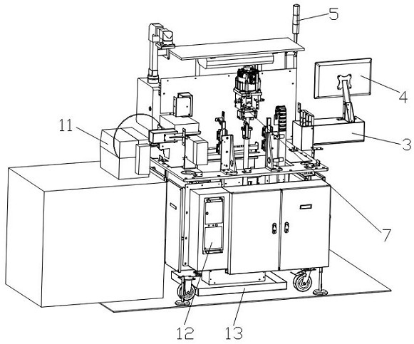
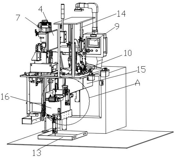
[0035] Such as figure 1 As shown, the bottom of the rack is a closed box structure. In the figure, it is hollowed out for the convenience of observing the structural distribution inside the rack. The left side of the frame is provided with a main control cabinet 1 and an air source box 2, the air source box 2 is located at the front side of the main control cabinet 1, and the operating end of the main control cabinet 1 is located on the left surface of the frame. On the left side of the upper end of the rack is placed a withstand voltage instrument 3, on the upper surface of the withstand voltage instrument 3 is placed an industrial computer display 4, on the left side of the upper end of the rack there is also a tower light 5, and the tower light 5 extends upward to the upper end of the rack ceiling . A resistance meter 8, a code scanning gun 10 and a printer 11 are placed on the right side of the upper end of the frame, and a main control panel 9 is arranged above the code ...
Embodiment 2
[0052] This embodiment differs from the other embodiments in that the linear guide rail 14 is a multi-step guide rail, that is, the linear guide rail 14 has two moving ends, wherein the main moving end is connected to the working chamber 15 and the auxiliary moving end is connected to the tooling 6 .
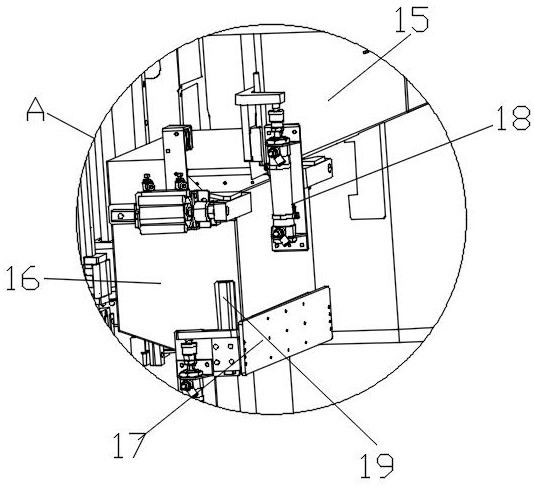
[0053] The implementation of this embodiment is different from Embodiment 1 in that the initial position of the working chamber 15 in this embodiment is close to the inner surface of the frame, that is, there is no steel grit dumped by the transport vehicle 16 between the working chamber 15 and the upper end of the frame. gap, the upper edge of the working chamber 15 is close to the inner surface of the frame. The motion trajectory of step S2 is as follows: after the detection piece is installed on the tooling 6, the linear guide rail 14 works, and the working chamber 15 at the main moving end moves down, so that there is enough space above the working chamber 15 for the transpor...
Embodiment 3
[0057] This embodiment is different from embodiments 1 and 2 in that the implementation mode in this embodiment is:
[0058] The detection method of the flexible connection copper bar withstand voltage test equipment for new energy vehicles, the steps include
[0059] S1, the detection piece is transferred to the resistance meter 8, and the resistivity of the detection piece is measured, and the qualified detection piece saves the data by number in the temporary database of the industrial computer 12;
[0060] S2. Install the detection piece on the tooling 6, one end of the detection piece is connected to the output detection voltage of the pressure-resistant machine, and the other end is blocked with a polyurethane sleeve;
[0061] S3, the tooling 6 is placed in the working room 15, and the conductive steel sand fills the working room 15;
[0062] S4, the withstand voltage test is turned on, and the qualified test piece saves the data in the temporary database of the industr...
PUM
 Abstract
Description
Claims
Application Information
 - R&D
- Intellectual Property
- Life Sciences
- Materials
- Tech Scout
- Unparalleled Data Quality
- Higher Quality Content
- 60% Fewer Hallucinations
Browse by: Latest US Patents, China's latest patents, Technical Efficacy Thesaurus, Application Domain, Technology Topic, Popular Technical Reports.
© 2025 PatSnap. All rights reserved.Legal|Privacy policy|Modern Slavery Act Transparency Statement|Sitemap|About US| Contact US: help@patsnap.com


