
Microphone with double back polar plates and manufacturing method thereof

A manufacturing method and a technology for a back plate, applied in the field of microphones, can solve the problems of inability to transmit signals, warping of the gold conductive layer, open circuits, etc., and achieve the effects of good filling effect, high consistency, and improved yield and reliability.

Pending Publication Date: 2022-04-29
MEMSENSING MICROSYST SUZHOU CHINA
View PDF0 Cites 0 Cited by
  • Summary
  • Abstract
  • Description
  • Claims
  • Application Information

AI Technical Summary

Problems solved by technology

Due to the use of gold material, there is abnormal stress at the interface between the gold conductive layer and each layer of semiconductor material, which will cause the gold conductive layer on the product to warp, which will cause the circuit to open and cause the signal to fail to transmit

Method used


Image

  • Microphone with double back polar plates and manufacturing method thereof
  • Microphone with double back polar plates and manufacturing method thereof
  • Microphone with double back polar plates and manufacturing method thereof

Examples


Embodiment Construction

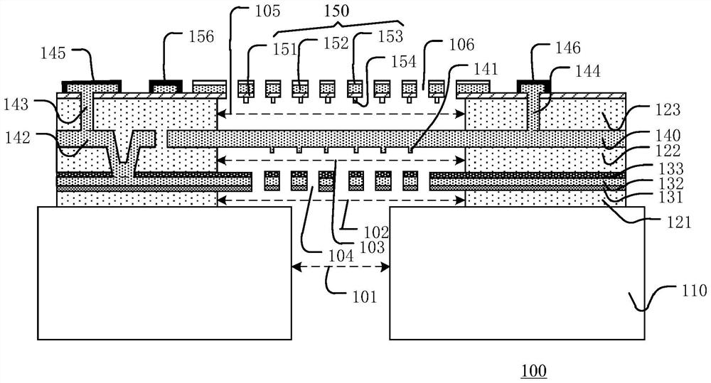
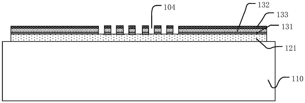
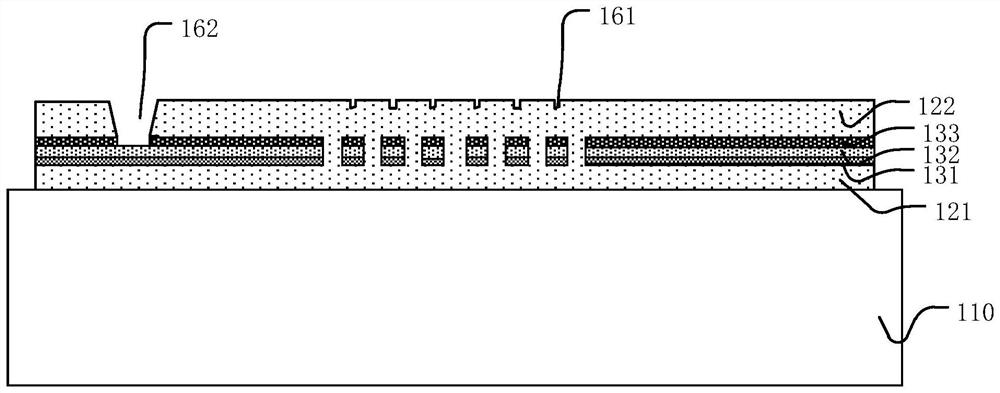
[0029] Hereinafter, the present invention will be described in more detail with reference to the accompanying drawings. In the various figures, identical elements are indicated with similar reference numerals. For the sake of clarity, various parts in the drawings have not been drawn to scale. Also, some well-known parts may not be shown. For the sake of simplicity, the semiconductor structure obtained after several steps can be described in one figure.

[0030] It should be understood that when describing the structure of a device, when a layer or a region is referred to as being "on" or "over" another layer or another region, it may mean being directly on another layer or another region, or Other layers or regions are also included between it and another layer or another region. Also, if the device is turned over, the layer, one region, will be "below" or "beneath" the other layer, or region.

[0031] If it is to describe the situation directly on another layer or anothe...


PUM


Abstract

The microphone comprises a substrate, a first sacrificial layer, a lower back polar plate, a second sacrificial layer, a vibrating diaphragm, a third sacrificial layer and an upper back polar plate which are sequentially stacked from bottom to top, the first conductive channel downwards penetrates through the second sacrificial layer from the surface of the second sacrificial layer to the lower back electrode plate; the second conductive channel penetrates through the third sacrificial layer and is connected with the first conductive channel; the first electrode and the third electrode are isolated from each other and located on the upper back pole plate, the first electrode is electrically connected with the lower back pole plate through the second conductive channel and the first conductive channel, and the third electrode is electrically connected with the upper back pole plate. According to the microphone with the double back polar plates, the electrode on the lower back polar plate and the electrode of the vibrating diaphragm are connected to the upper back polar plate when the vibrating diaphragm and the upper back polar plate layer are deposited, so that the adhesive force between the conductive channel and the lower back polar plate and the vibrating diaphragm is improved, and the yield and the reliability of a device are improved.

Description

technical field [0001] The invention relates to the technical field of microphones, in particular to a double back plate microphone and a manufacturing method thereof. Background technique [0002] Microphone products with double back plates are widely used at this stage due to their high sensitivity and good reliability. The double-back plate microphone structure is connected through the lower back plate electrode, the diaphragm layer electrode, and the upper back plate electrode, and then the signal on the microphone is input to the control chip through the wire bonding process, and the control chip processes the input signal. In the prior art, the back plate electrode and the diaphragm electrode are connected to the surface of the upper back plate by depositing a gold conductive layer, so that the heights of the three pads (pads) are consistent, and the wiring yield of the product is improved. Due to the use of gold material, there is abnormal stress at the interface bet...

Claims


Application Information

Patent Timeline
IPC IPC(8): H04R31/00H04R7/10B32B3/08B32B9/00B32B9/04
CPCH04R31/003H04R7/10B32B9/00B32B9/04B32B3/08H04R2231/001H04R2307/00
Inventor 孟燕子荣根兰
Owner MEMSENSING MICROSYST SUZHOU CHINA
Learn More