Method for removing sulfide in liquefied gas
A technology for liquefied gas and sulfide, which is applied in chemical instruments and methods, separation methods, gas fuels, etc., and can solve problems such as the reduction of olefin yield.
- Summary
- Abstract
- Description
- Claims
- Application Information
AI Technical Summary
Problems solved by technology
Method used
Image
Examples
Embodiment 1
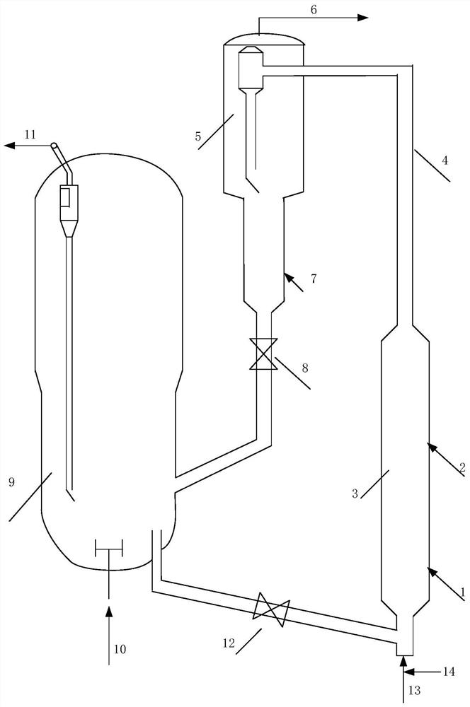
[0074] This embodiment is used to illustrate the method for removing sulfide in liquefied gas disclosed in the present disclosure, including the following operations.
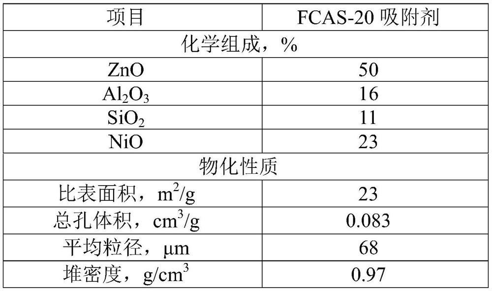
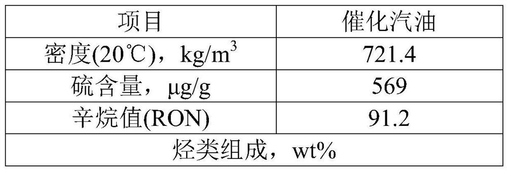
[0075] (1) In the fast bed desulfurization reactor, under the action of the lifting medium (water vapor), the regenerated desulfurization adsorbent that is completely burnt and regenerated is mixed with gasoline (catalytic gasoline with a sulfur content of 569 μg / g and a weight hourly space velocity of 1.3h -1 ) is contacted below the height of a given position in the extension, and passivated to obtain a passivated regenerated desulfurization adsorbent, wherein the weight ratio of the completely charred regenerated desulfurization adsorbent to catalytic gasoline is 8:1;
[0076] (2) Liquefied gas (catalytically cracked liquefied gas) and refinery gas containing hydrogen are introduced at a given height in the extension of the fast bed desulfurization reactor, and liquefied gas (catalytically cracked liquefied ...
Embodiment 2
[0082] The method for removing sulfides in liquefied gas according to the method of Example 1, the difference is: during passivation, the gasoline space velocity is 0.7h -1 ; The temperature of adsorption desulfurization reaction is 430℃, the pressure is 2.0MPa, and the weight hourly space velocity of liquefied gas is 1.4h -1 .
[0083] Physical and chemical analysis was carried out on the desulfurized oil and gas materials obtained in this example, and the sulfur content, olefin content and octane number were measured. The measurement results are shown in Table 4.
Embodiment 3
[0085] This embodiment is used to illustrate the method for removing sulfide in liquefied gas disclosed in the present disclosure, including the following operations.
[0086] (1) Use the semi-regenerated desulfurization adsorbent regenerated by incomplete charring as the passivated regenerated desulfurization adsorbent, and in the fast bed desulfurization reactor, under the action of the lifting medium (water vapor), the passivated regenerated desulfurization adsorption The agent is contacted with liquefied gas (catalytically cracked liquefied gas) and refinery gas containing hydrogen to carry out the adsorption desulfurization reaction to obtain the reacted material, wherein the weight ratio of the semi-regenerated desulfurization adsorbent that is not completely burnt and regenerated to the liquefied gas is 16:1, the conditions of adsorption desulfurization reaction include: temperature is 400°C, pressure is 1.0MPa, liquefied gas weight hourly space velocity is 2.6h -1 , th...
PUM
 Abstract
Description
Claims
Application Information
 - R&D
- Intellectual Property
- Life Sciences
- Materials
- Tech Scout
- Unparalleled Data Quality
- Higher Quality Content
- 60% Fewer Hallucinations
Browse by: Latest US Patents, China's latest patents, Technical Efficacy Thesaurus, Application Domain, Technology Topic, Popular Technical Reports.
© 2025 PatSnap. All rights reserved.Legal|Privacy policy|Modern Slavery Act Transparency Statement|Sitemap|About US| Contact US: help@patsnap.com


