Computer peripheral equipment hardware fitting machining device
A technology of peripheral equipment and processing equipment, which is applied in the field of processing equipment for hardware accessories of computer peripheral equipment, can solve the problems of easy clogging of grinding tools by scrap materials and low automation efficiency, and achieve the effects of reducing manual operations, avoiding clogging, and reducing labor intensity
- Summary
- Abstract
- Description
- Claims
- Application Information
AI Technical Summary
Problems solved by technology
Method used
Image

Examples
Embodiment 1
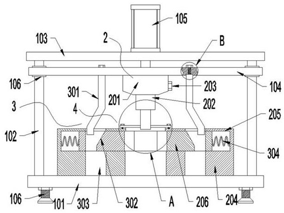
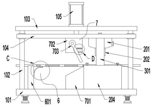
[0030] like figure 1 , figure 2 and Figure 7 As shown, a hardware accessories processing device for computer peripheral equipment, including a mounting plate 101, also includes:
[0031] Support column 102, top plate 103, push plate 104, telescopic device 105, punching assembly 2, base 204, punching die 206, mold opening assembly 3, pressing assembly 4, one-way movement assembly 6 and feeding and conveying assembly 7;
[0032] The support column 102 is fixedly installed on the mounting plate 101, the top plate 103 is fixedly installed on the end of the support column 102, the push plate 104 is slidably connected with the support column 102, and the telescopic device 105 is fixedly installed on the top plate 103, The telescopic end of the telescopic device 105 is fixedly connected with the push plate 104, the base 204 is fixedly installed on the mounting plate 101, the base 204 chute 205 is provided, the punching die 206 is provided with two, the The punching die 206 is pr...
Embodiment 2
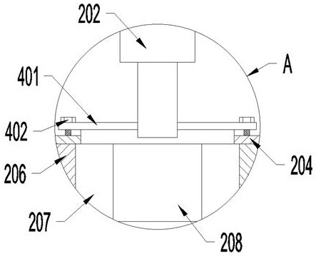
[0036] like Figure 1-Figure 3As shown, in the second embodiment, the difference from the above embodiment is that the punching assembly 2 includes a fixed block 201 and a punching block 202, the base 204 is provided with a blanking port 208, and the fixed block 201 is fixed Installed on the push plate 104, the punching block 202 is installed on the push plate 104, the fixed block 201 is provided with a pressing block installation groove, the punching block 202 is arranged in the pressing block installation groove, the fixed A fastening screw 203 is threadedly connected to the block 201 , and one end of the fastening screw 203 is against the punching block 202 .
[0037] When the push plate 104 moves downward, it drives the fixed block 201 to move downward, and the fixed block 201 drives the punching block 202 to move downward, and the punching block 202 cooperates with two punching dies 206 to punch the hardware accessories.
Embodiment 3
[0039] like Figure 1-Figure 4 As shown, in the third embodiment, the difference from the above embodiments is that the mold opening assembly 3 includes a side push plate 301, a first tension spring 304, and an escape groove 303 is provided on the base 204, and the two Punching die 206 is provided with side pushing groove 302, and described side pushing plate 301 is provided with two, and two described side pushing plates 301 are all installed on the pushing plate 104, and described first tension spring 304 is provided with two. The two first tension springs 304 are respectively arranged at both ends of the side push groove 302, the push plate 104 is provided with an installation groove 501, and the side push plate 301 is arranged in the installation groove 501, and the side A second mounting screw 502 is threadedly connected to the push plate 301 .
[0040] When the push plate 104 moves downward, it drives the side push plate 301 to move downward, and the side push plate 301...
PUM
 Abstract
Description
Claims
Application Information
 - R&D
- Intellectual Property
- Life Sciences
- Materials
- Tech Scout
- Unparalleled Data Quality
- Higher Quality Content
- 60% Fewer Hallucinations
Browse by: Latest US Patents, China's latest patents, Technical Efficacy Thesaurus, Application Domain, Technology Topic, Popular Technical Reports.
© 2025 PatSnap. All rights reserved.Legal|Privacy policy|Modern Slavery Act Transparency Statement|Sitemap|About US| Contact US: help@patsnap.com