Double-gantry type high-rigidity ram machining device

A processing device and high-rigidity technology, applied in metal processing equipment, metal processing machinery parts, manufacturing tools, etc., can solve the problems of increased motor speed, long duration, large stator current, etc., to reduce response time and prevent burning Damaged coils, the effect of improving machining accuracy

Active Publication Date: 2022-05-06
南通固邦数控机床有限公司
View PDF19 Cites 0 Cited by
  • Summary
  • Abstract
  • Description
  • Claims
  • Application Information

AI Technical Summary

Problems solved by technology

[0004] The above-mentioned patents have the following disadvantages: the rotation between the motor and the main shaft is rigidly connected, and due to the quality of the main shaft itself and the quality of the tool clamped by the fixture, the entire The moment of inertia of the main shaft part is large, and when the motor is initially started, the large moment of inertia of the main shaft causes the speed of the motor to increase slowly, making the current in the stator large and lasts for a long time. During assembly line processing, when the motor starts repeatedly, It is easy to cause the coil to burn out

Method used


Image

  • Double-gantry type high-rigidity ram machining device
  • Double-gantry type high-rigidity ram machining device
  • Double-gantry type high-rigidity ram machining device

Examples


Embodiment 1

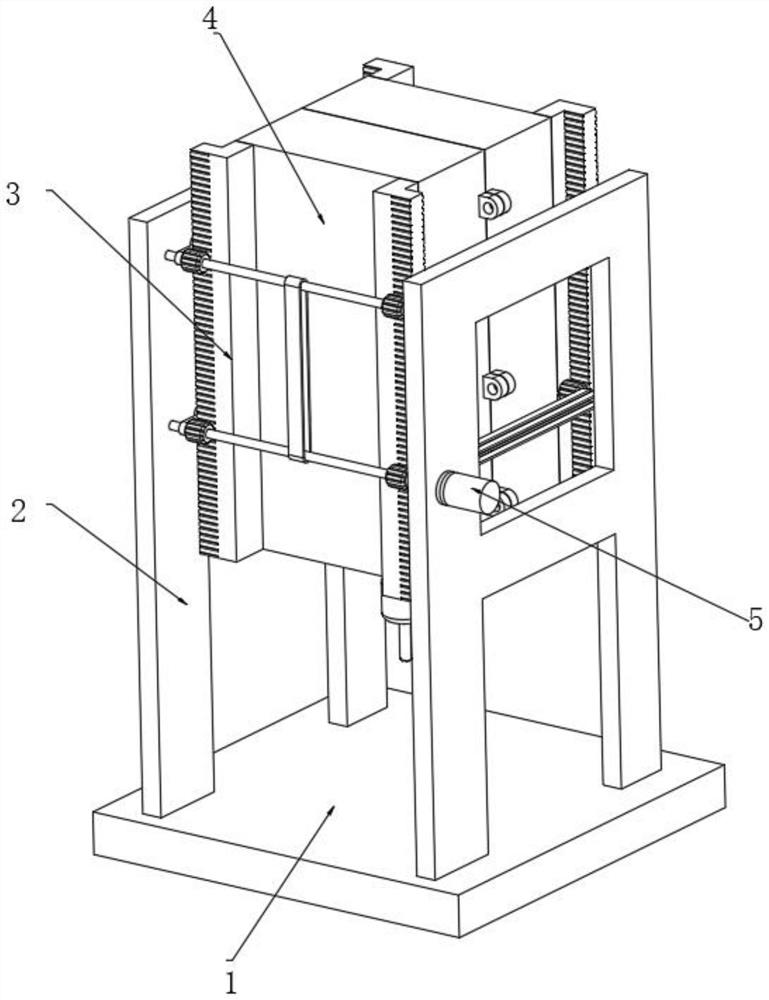
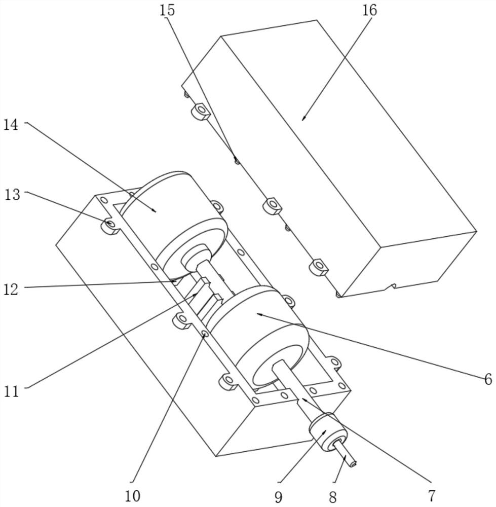
[0042] A double gantry type high rigidity ram processing device, such as Figure 1-8 As shown, it includes a workbench 1, two gantry frames 2 for support, a ram 4 connected to the inside of the gantry frame 2 through two sets of linear lifting parts 3 and a ram 4 linearly slidingly connected to the inside of the gantry frame 2, and a processing part arranged inside the ram 4. The processing part includes a spindle motor 14 for power supply, a spindle 7 for output power, a tool 8 coaxially connected to the spindle 7 through a clamp 9 and used for processing, and a buffer 6 for connecting the spindle motor 14 and the spindle 7 .

[0043] In order to solve the problem of instantaneous load at startup; Figure 4 As shown, the buffer 6 includes a driving casing 25 and a driven casing 27 that are connected to each other in a sealed rotation through a sealing swivel 26 and filled with oil, and the outer walls of the driving casing 25 and the driven casing 27 are welded. For connect...

Embodiment 2

[0049] A double gantry type high rigidity ram processing device, such as figure 2 As shown, in order to solve the problem of convenience; this embodiment makes the following improvements on the basis of Embodiment 1: the ram 4 includes two half-shells 16 fixed to each other by flange ears 13, and one of the half-shells 16 The inner wall of the housing 16 is provided with a limit hole 10, and the outer wall of the other half shell 16 is welded with a limit post 15 that matches the limit hole 10; by dividing the ram 4 into two half shells 16 , on the one hand, it makes installation and disassembly more convenient, on the other hand, they are all cavity type, and their own weight is low, so that the elastic deformation caused by their own weight is small, and the rigidity is indirectly increased, and because the limit post 15 and the limit hole 10 The cooperation can limit the relative position of the two half-shells 16, and the limit positions are all in surface contact, which ...

Embodiment 3

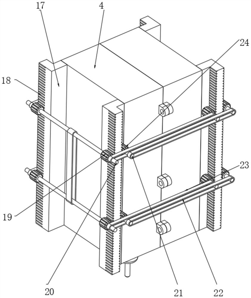
[0053] A double gantry type high rigidity ram processing device, such as figure 2 As shown, in order to solve the problem of accuracy; this embodiment makes the following improvements on the basis of Embodiments 1 and 2: the linear lifting part 3 includes a support plate 17 welded to the four corners of the ram 4 outer walls and a support plate 17 provided through the support plate Teeth 18 are meshed with gear one 19 and gear two 24 on both sides of support plate 17. The gear one 19 located on the same side and at the same height is connected by shaft one 20, and is connected to the gantry 2 through shaft one 20 in rotation. The inner wall, the gear two 24 is connected to the inner wall of the gantry 2 through the shaft two 21, and the shaft one 20 and the shaft two 21 on the same side of the support plate 17 are respectively driven and matched with the synchronization component two 23 through the synchronization component one 22. In the embodiment, the specific types of the...


PUM


Abstract

The invention discloses a double-gantry type high-rigidity ram machining device, and relates to the technical field of machining. The problem that initial starting is complex is solved. The machine specifically comprises a workbench, two portal frames which are supported and fixedly installed on the outer wall of the top of the workbench, a ram which is linearly and slidably connected to the inner sides of the portal frames through two sets of linear lifting parts, and a machining part which is arranged in the ram. The machining part comprises a spindle motor used for providing power, a spindle used for outputting power, a cutter coaxially connected to the spindle through a clamp and used for machining, and a buffer used for connecting the spindle motor and the spindle. And the buffer comprises a driving shell and a driven shell which are mutually sealed and rotationally connected through a connecting sealing swivel and are filled with oil. When the main shaft motor is initially started, the influence of the rotational inertia of the main shaft is less, and the rated rotating speed can be reached in a short time, so that the initial starting load is reduced, the coil is prevented from being burnt out, and the safety performance is improved.

Description

technical field [0001] The invention relates to the technical field of mechanical processing, in particular to a double-gantry type high-rigidity ram processing device. Background technique [0002] The ram part is an important part of the gantry CNC milling machine. Through this component machine tool, the transmission and output of the spindle power are realized, thereby realizing the cutting function of the machine tool. [0003] After searching, the Chinese Patent Publication No. is CN211915639U, which discloses a high-rigidity ram structure for a gantry milling machine, including a spindle box. Balance cylinder rods are symmetrically arranged on both sides of the spindle box, and a spindle motor is arranged on the top of the spindle box. , there is a cavity inside the spindle box, and the carbon fiber coupling and the main shaft are arranged in sequence from top to bottom in the cavity, wherein the main shaft motor and the main shaft are connected through the carbon fi...

Claims


Application Information

Patent Timeline
Patent Type & Authority Applications(China)
IPC IPC(8): B23Q11/00
CPCB23Q11/00
Inventor 张守力刘福江张振
Owner 南通固邦数控机床有限公司
Why Eureka
Try Eureka