
Device and method for driving torpedo anchor through spiral dumping

A technology for torpedo anchors and soil dumping, which is used in anchor points, transportation and packaging, ship construction, etc., can solve the problems of insufficient initial penetration depth of torpedo anchors, inability to fully exert the bearing capacity of torpedo anchors, and loose penetration of soil layers. The effect of saving transportation and installation costs, reducing forward propulsion resistance, and reducing material usage

Active Publication Date: 2022-05-06
NANJING FORESTRY UNIV
View PDF7 Cites 0 Cited by
  • Summary
  • Abstract
  • Description
  • Claims
  • Application Information

AI Technical Summary

Problems solved by technology

[0006] The object of the present invention is to solve the deficiencies and defects of the prior art, and provides a device and method for driving torpedo anchors by spiral soil removal. The method continuously transports the soil in front of the anchor head to the tail, and continuously pushes the torpedo anchor forward to reach a suitable stratum or a suitable depth for final positioning, so that the bearing capacity can be effectively exerted; solve the torpedo anchor The initial penetration depth is insufficient, or the torpedo anchor cannot fully exert the bearing capacity due to the penetration into the soil layer is too loose

Method used


Image

  • Device and method for driving torpedo anchor through spiral dumping
  • Device and method for driving torpedo anchor through spiral dumping
  • Device and method for driving torpedo anchor through spiral dumping

Examples


Embodiment Construction

[0038] The present invention will be further described below in conjunction with the accompanying drawings and embodiments.

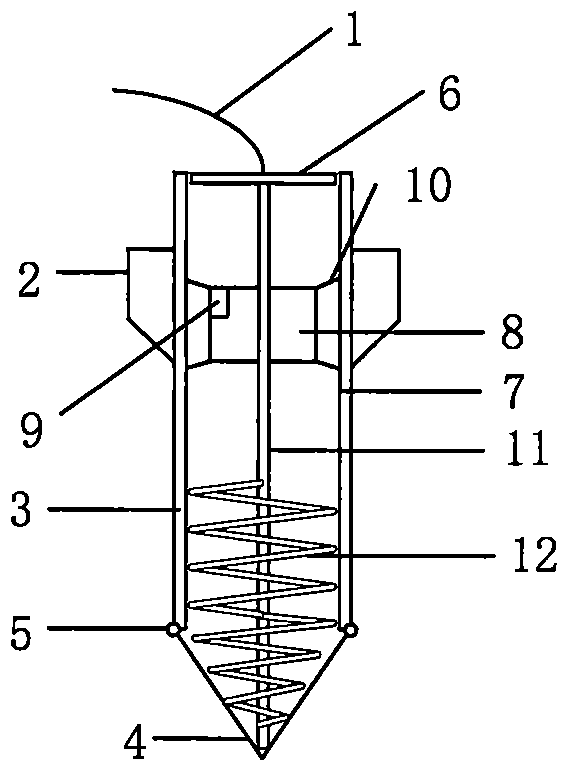
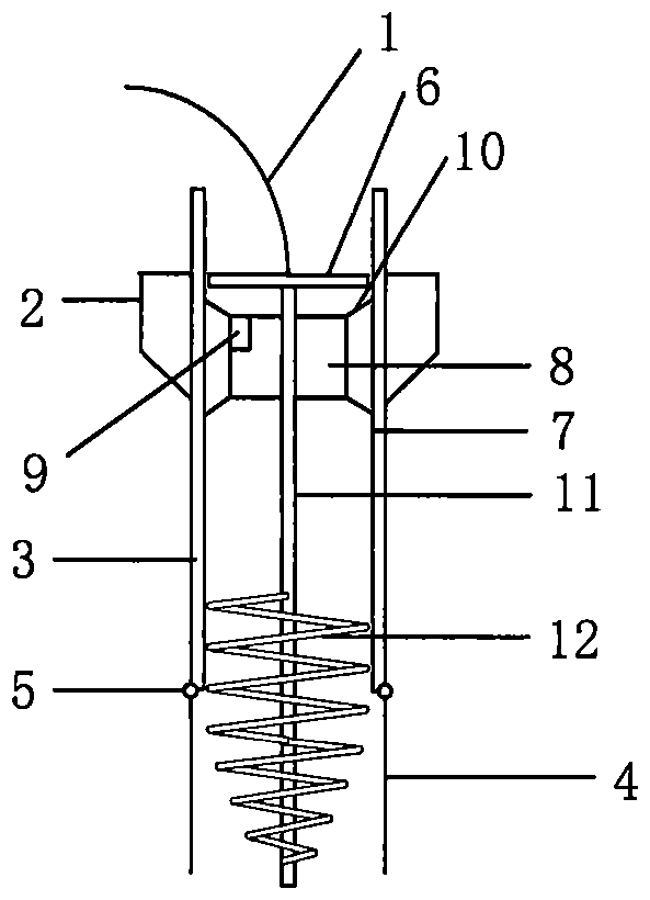
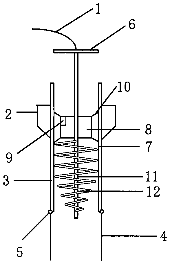
[0039] Such as figure 1 As shown, a device for driving a torpedo anchor by spiral dumping includes an anchor chain 1, an empennage 2, an anchor body 3, an anchor head 4, a hinge point 5, a tail plate 6, a hollow pipe 7, a stepping motor 8, a battery 9, Steel bar 10, rotating shaft 11, spiral plate 12;

[0040] The anchor body 1 and the anchor head 4 are connected by a hinge point 5;

[0041] The anchor chain 1 is connected to the external midpoint of the tail plate 6;

[0042] The battery 9 is installed inside the stepper motor 8;

[0043] The empennage 2 is welded to the tail of the anchor body 3 in a cross-shaped arrangement;

[0044] The tail plate 6 is welded together with the rear end of the rotating shaft 11, and is installed in the center of the hollow pipe 7. The diameter of the tail plate 6 is consistent with the inner diameter of the hollo...


PUM


Abstract

The invention provides a device and method for driving a torpedo anchor through spiral dumping. The device comprises an anchor chain, a tail wing, an anchor body, an anchor head, a hinge point, a tail plate, a hollow pipeline, a stepping motor, a battery, a reinforcing bar, a rotating shaft and a spiral plate. The rear end of the rotating shaft is connected with the tail plate, and the front end of the rotating shaft is connected with the spiral plate; the stepping motor is fixed to the upper portion of the hollow pipeline through a steel bar. The battery is mounted in the stepping motor; a stepping motor is mainly used for driving a combination formed by a spiral plate, a rotating shaft and a tail plate to conduct reciprocating earth cutting and dumping operation, the torpedo anchor is continuously propelled towards the seabed, and the problem that the penetration depth of the torpedo anchor is insufficient or the problem that the penetration soil layer is too loose and is not beneficial to exerting the bearing capacity of the torpedo anchor is solved. As the torpedo anchor can be tunneled, the penetration depth can be increased without excessively depending on the gravity of the torpedo anchor, the lightweight manufacturing of the torpedo anchor can be realized, the material consumption is reduced, and the manufacturing cost and the transportation and installation cost are saved.

Description

technical field [0001] The invention belongs to the technical field of mooring foundation devices, and in particular relates to a device and method for driving torpedo anchors by spiral soil removal. Background technique [0002] my country's marine resources exploration is moving towards the deep sea, which puts forward high requirements for offshore oil platforms and platform anchoring foundations. At present, the widely used deepwater anchor foundations mainly include suction anchors, normal load-bearing anchors, suction penetration plate anchors, vibration deep buried anchors, and dynamic penetration anchors. Among them, the torpedo anchor is the latest form of deep-sea anchor foundation. It has outstanding features such as low cost, simple and efficient installation, and good anchoring performance. Deep water anchor foundation. The problem encountered at present is that the torpedo anchor mainly relies on its own gravity to penetrate the soil, but the penetration dept...

Claims


Application Information

Patent Timeline
Patent Type & Authority Applications(China)
IPC IPC(8): B63B21/26
CPCB63B21/26Y02A40/81
Inventor 刘成索坤宇朱悦悦蔡光华葛琦
Owner NANJING FORESTRY UNIV
Learn More