[0016] In order to make the purpose, technical solutions and advantages of the embodiments of the present invention clearer, the following will clearly describe the technical solutions in the embodiments of the present invention in conjunction with the drawings in the embodiments of the present invention. Obviously, the described embodiments are the Some, but not all, embodiments are invented. Based on the embodiments of the present invention, all other embodiments obtained by persons of ordinary skill in the art without making creative efforts belong to the protection scope of the present invention.
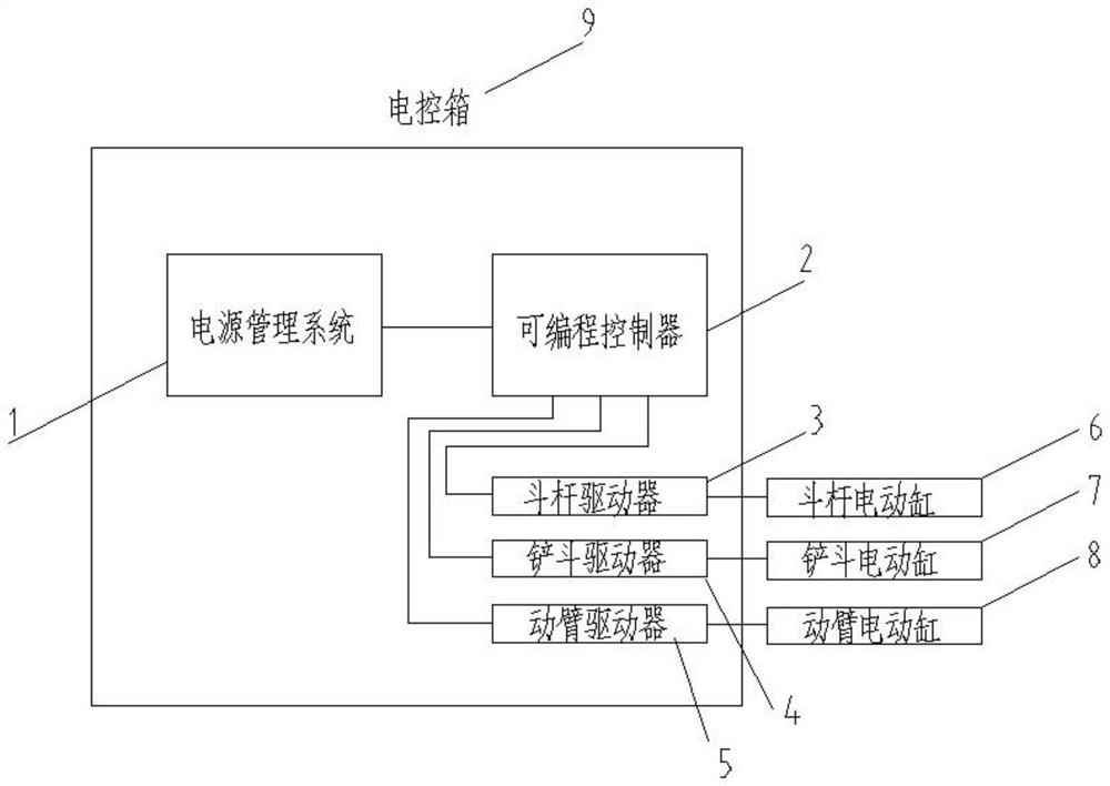
[0017] according to figure 1 As shown, the programmable controller 2 is connected with the stick driver 3, the bucket driver 4, and the boom driver 5 through a communication cable, and the stick driver 3, the bucket driver 4, and the boom driver 5 are connected to the The arm electric cylinder 6, the bucket electric cylinder 7, and the boom electric cylinder 8 are connected through a power cable, an encoder cable and a limit switch cable.
[0018] according to figure 2 As shown, the stick electric cylinder 6, bucket electric cylinder 7, and boom electric cylinder 8 all adopt this type of structure, including a motor 61, a reducer 62, a gear box 63, a lower lug 64, and a gear set 65 , bearing housing 66, thrust self-aligning roller bearing 67, ball screw pair 68, push rod 69, cylinder barrel 610, limit switch 612, front end cover 613, upper lug 614, the motor 61 and the reducer 62 pass through Keys and screws are connected, the left end of the ball screw pair 68 is installed with the thrust self-aligning roller bearing 67, the screw nut is connected with the push rod 69 through screws, and the right end of the push rod 69 is equipped with the upper Lug 614; the outer ring of the thrust self-aligning roller bearing 67 is installed in the bearing seat 66, the bearing seat 66 is connected to the cylinder 610 by screws, and the other end of the cylinder 610 is connected to the front end The cover 613 is connected by screws, and the cylinder 610 is provided with an electrical limit switch assembly 611 to ensure that when the push rod is lifted out and retracted, the cylinder assembly will not be damaged due to stroke overshoot.
[0019] according to image 3 As shown, the power management system includes a circuit breaker 11, a power protector 12, an electromagnetic filter 13, a contactor 14, a rectification filter circuit 15, a protection circuit 16, an IGBT 17, a communication circuit 18, a single-chip microcomputer 19, and a cooling module 20. The above-mentioned power management system can intelligently control the power supply and distribution of the excavator, and the on-off control of the power supply of each circuit is carried out through the IGBT17. Under the input of various power sources such as commercial power, diesel engine, battery pack, etc., the machine meets the power supply requirements of each equipment.
[0020] according to Figure 4 As shown, the simulation algorithm includes ant colony algorithm, genetic algorithm, particle swarm algorithm, fish swarm algorithm and simulated annealing algorithm, etc., and the convergence curve of the objective function in the operation process is shown in the above-mentioned simulation algorithm convergence schematic diagram; The constraint functions of the simulation algorithm are the speed and thrust range of the stick electric cylinder, the speed and thrust range of the bucket electric cylinder, the speed and thrust range of the boom electric cylinder, the relationship between the stick electric cylinder speed and the boom electric cylinder speed, The relationship between the speed of the stick electric cylinder and the speed of the bucket electric cylinder, the relationship between the speed of the boom electric cylinder and the speed of the bucket electric cylinder; the objective function of the simulation algorithm is that the maximum power required by all electric cylinders is not greater than that of the power management system The maximum power that can be output can ensure the smooth operation of the system.
[0021] Further, the arm electric cylinder 6, bucket electric cylinder 7, and boom electric cylinder 8 check the strength and life of each component, select components that can meet the use, and carry out standardized design and long-life design for each component And lightweight design, the cylinder is preferably made of standard aluminum alloy profiles, which greatly reduces the cost, and finally improves the performance while reducing the price of the entire electric cylinder power matching control system for excavators based on programmable controllers, providing A low-cost, safe and reliable electric cylinder for excavators is developed.
[0022] Further, the programmable controller-based electric cylinder power matching control system for excavators is preferably a ball screw, followed by a planetary roller screw, which can realize high-efficiency operation of the excavator and reduce power consumption.
[0023] Further, key grooves are provided on both sides of the inner wall of the cylinder for radial limit, and limit switches 611 are set at the limit positions of the upper and lower ends to protect the safe use of the electric cylinder for excavators.
[0024] Further, the power management system can perform local button control or remote operation through the communication circuit 18. The buttons can be switched between remote and local, and the buttons are locked to each other to avoid damage to equipment due to misoperation. The control system is simple and efficient .
[0025] Further, the control system components are selected from wide-temperature electrical components, and the control circuit components are installed and fixed in the electric control box, and the external cables are connected by electrical connectors, which can be adapted to high and low temperature, dust, rain, wading Various complex environments such as water and high altitude.
[0026] Although this article uses more terms such as programmable controller, power management system, stick driver, bucket driver, boom driver, stick electric cylinder, bucket electric cylinder, boom electric cylinder, electric control box, etc. The possibility of using other terms is not excluded. These terms are only used to describe and explain the essence of the present invention more conveniently, and it is against the spirit of the present invention to interpret them as any additional limitation. The specific embodiments described herein are merely illustrative of the spirit of the invention. Those skilled in the art to which the present invention belongs can make various modifications or supplements to the described specific embodiments or adopt similar methods to replace them, but they will not deviate from the spirit of the present invention or go beyond the definition of the appended claims range.