Unloading valve and combination valve type buffer oil cylinder

A buffer cylinder and unloading valve technology, which is applied in the field of hydraulic cylinders and hydraulic valves, can solve the problems of reducing the mechanical collision strength of cylinder pistons, misoperation of buffer valves, and reducing buffering effects, so as to avoid power consumption and system heating, and buffer control The effect of stability and outstanding cushioning effect

Pending Publication Date: 2022-05-06
QINGDAO ACME INNOVATION TECH CO LTD
View PDF6 Cites 1 Cited by
  • Summary
  • Abstract
  • Description
  • Claims
  • Application Information

AI Technical Summary

Problems solved by technology

[0003] The above technology has reduced the mechanical collision strength of the cylinder piston to a certain extent and played a certain buffering role, but there are still the following deficiencies: because the pressure of the oil cylinder inlet chamber is not unloaded during the buffering process, the oil cylinder is passing through the oil return chamber. While throttling prevents the piston from moving, the oil inlet chamber at the other end of the piston still continues to work to provide power to the piston, and the system pressure will also rise with the sudden rise of the buffer pressure to form a system pressure shock, resulting in unnecessary pressure on the oil inlet chamber. Power consumption and energy waste increase the system heat and reduce the buffering effect
[0004] Patents CN201610419750.1, CN202010751295.1 and CN202021559346.2 effectively solve the above problems in the prior art by setting buffer valves to control the throttling of the oil return chamber of the oil cylinder and the unloading of the oil inlet chamber, but the throttling control is mainly through A small amount of oil is isolated from the cylinder chamber through a separate signal device as the output signal oil to control the movement of the valve core, and dynamically adjust the size of the throttle port and unloading port of the buffer valve. However, due to the signal The amount of oil is small and there are many and sensitive factors that affect the signal oil flow and pressure, so it is difficult to control to an ideal state, and it is easy to generate large pressure fluctuations, causing the valve core to move up and down, and the throttle port The steady-state performance of the cushion valve becomes worse, and the fluctuation of the throttle port and the unloading port of the buffer valve will react on the signal oil of the control spool, which will further affect the steady-state performance of the buffer valve, thereby affecting the adjustment quality of the throttle port
At the same time, the anti-interference ability of the valve needs to be improved. During the normal operation of the oil cylinder, when the abnormal movement of the spool caused by pressure fluctuations exceeds a certain amplitude and causes oil return throttling, the pressure difference generated by the throttling will further promote The spool continues to move in an unexpected direction, resulting in misoperation of the cushion valve and affecting the normal use of the cylinder
In summary, the spring stiffness, the throttle port of the buffer valve, the unloading port, the damping hole, and the cross-sectional area of ​​the signal cavity are all factors that affect the dynamic characteristics and stability of the buffer valve. The volume is not easy to control, so the adjustment and control of the buffer valve becomes very complicated, and there is still a large room for improvement in the quality and stability of the buffer; and because the diameter of the spool will affect the flow of the main oil passage, the small diameter design cannot be adopted. Therefore, the diameter of the spool and the structure of the valve are too large, the structure is complicated, the layout is difficult, and the cost is also high, so it needs to be improved.

Method used


Image

  • Unloading valve and combination valve type buffer oil cylinder
  • Unloading valve and combination valve type buffer oil cylinder
  • Unloading valve and combination valve type buffer oil cylinder

Examples


Embodiment 1

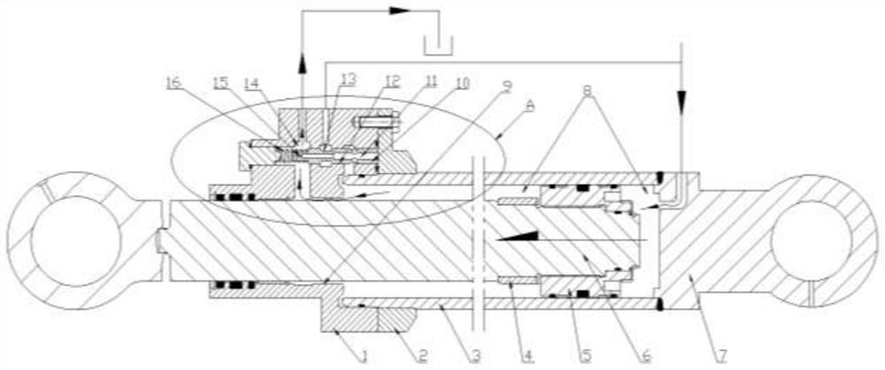
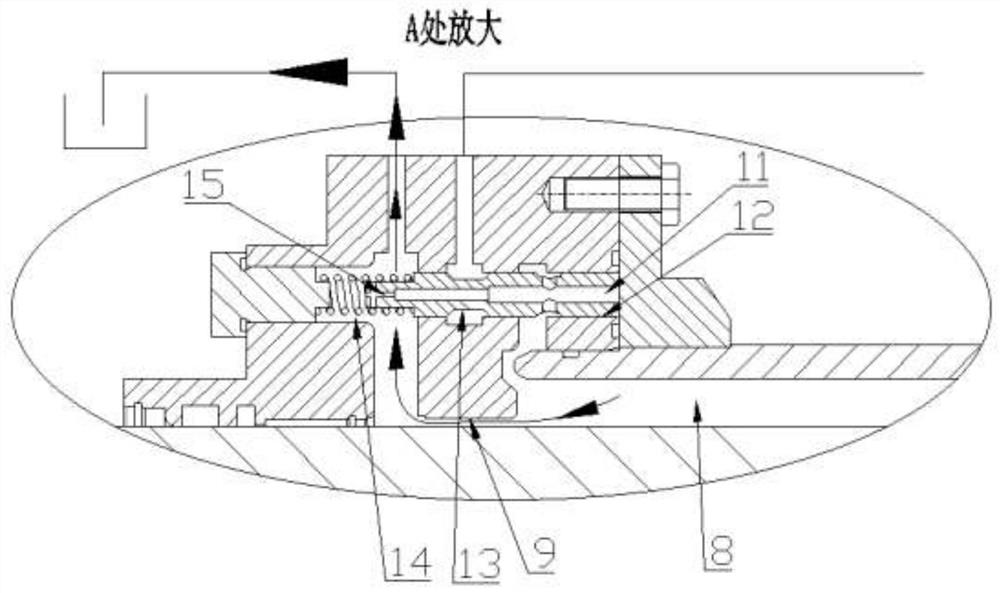
[0057] like Figure 1-4 As shown, a kind of unloading valve, the unloading valve is integrated on the guide sleeve of the oil cylinder, used in conjunction with the oil cylinder, can realize the unloading and buffering function of the oil cylinder, including the valve body, the valve core 10 and the return spring 16, the valve body is equipped with There is a valve hole 12, and the valve core is fitted in the valve hole. A driving cavity 11 of the valve core and a spring cavity 14 of the valve core are respectively formed at both ends of the valve hole. The return spring is arranged in the spring cavity, and one end thereof is compressed against At the bottom of the spring cavity, the other end is compressed against one end of the valve core, and under the thrust of the return spring, the other end of the valve core is pressed against the bottom of the drive cavity; the valve core is also provided with a damping hole 15 And the unloading groove 13, the driving chamber of the v...

Embodiment 2

[0064] like Figure 5 , Image 6 As shown in the figure, a combination valve type cushioning oil cylinder is provided with a combination valve only in the cylinder chamber at one end of the cylinder bottom, and the combination valve is integrated on the bottom of the cylinder, which can realize the cushioning of the oil cylinder at the bottom end of the cylinder. Figure 5 and Image 6 The structure is similar, only the location of the unloading valve is different. Compared with Example 1, the main difference is that: the valve hole of the unloading valve and the buffer chamber of the throttle valve are set on the bottom of the cylinder, and the buffer plug of the throttle valve is set at the center of the bottom of the piston rod. Similar to Example 1, it will not be repeated here.

Embodiment 3

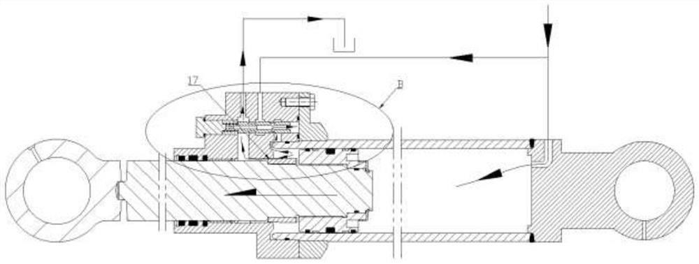
[0066] like Figure 7 As shown, a combination valve type buffer oil cylinder is equipped with combination valves at both ends of the oil cylinder, which can realize the buffer when the piston at any end of the oil cylinder is close to the end of the cylinder stroke. This embodiment is a composite structure of Embodiment 1 and Embodiment 2, which can realize the two-way buffering function of the oil cylinder. During the working process of the oil cylinder, when the piston is close to the stroke end of one end of the oil cylinder, only the combination valve arranged at the end of the oil cylinder is activated to play the buffer function.


PUM


Abstract

The invention relates to the field of hydraulic oil cylinders, in particular to an unloading valve and a combination valve type buffer oil cylinder, and the unloading valve comprises a valve body, a valve element and a return spring and is further provided with a damping hole and an unloading groove; the combination valve comprises an unloading valve and a throttling valve, and the throttling valve comprises a buffer plug and a buffer cavity; a piston rod assembly of the combination valve type buffering oil cylinder is installed in a cylinder body, the cylinder body comprises a cylinder head flange, a cylinder bottom and a cylinder barrel, and the piston rod assembly comprises a guide sleeve, a piston and a piston rod. The combination valve is arranged on the oil cylinder; according to the technical scheme, the unloading function of the oil inlet cavity is added, the buffering effect is outstanding, the buffering pressure is reduced, meanwhile, the system is in the unloading state in the buffering stage, energy loss and heating of the system are reduced, pressure impact caused by buffering to the system is avoided, the reliability of the system is improved, and the service life of the system is prolonged. And the difficulty of performance matching, mounting and debugging of the original cushion valve is reduced.

Description

technical field [0001] The invention relates to the field of hydraulic oil cylinders and hydraulic valves, in particular to an unloading valve and a combined valve type buffer oil cylinder. Background technique [0002] The oil cylinders of construction machinery are generally medium and high pressure heavy-duty oil cylinders. The working pressure is relatively high, and the inertia of the reciprocating parts of the oil cylinder is also relatively large. Occurs, and at the same time brings a large hydraulic shock, causing hydraulic system failure. The current solution is generally to add a buffer mechanism on the oil cylinder, that is, to set a buffer chamber at the end of the stroke of the cylinder, and to set a buffer plug on the piston rod. It forms a throttling effect, forcing the pressure of the oil return chamber of the oil cylinder to rise, using the back pressure of the oil return to prevent and reduce the movement speed of the piston, reducing the mechanical collis...

Claims


Application Information

Patent Timeline
IPC IPC(8): F15B15/14F15B15/20F15B15/22F16K15/02
CPCF15B15/1423F15B15/1471F15B15/202F15B15/224F16K15/025
Inventor 朱德伟荣晓瑜
Owner QINGDAO ACME INNOVATION TECH CO LTD
Why Eureka
Try Eureka