Damage positioning imaging method and system based on non-linear Lamb wave zero frequency component

A zero-frequency component, damage localization technology, used in the analysis of solids using sonic/ultrasonic/infrasonic waves, material analysis using sonic/ultrasonic/infrasonic waves, measurement devices, etc. Problems such as detection and complex operation

Active Publication Date: 2022-05-06
CHONGQING IND POLYTECHNIC COLLEGE
View PDF12 Cites 1 Cited by
  • Summary
  • Abstract
  • Description
  • Claims
  • Application Information

AI Technical Summary

Problems solved by technology

The above scheme adopts two sets of detection models without early fatigue damage and those with early fatigue damage. Through the matrix integral of the detection part of the two sets of detection models, the probability distribution map of the detection part with early fatigue damage is obtained. The above scheme uses two sets of models For group comparison, there is no definition standard for the model without early damage, and it is impossible to judge whether the model without early damage is really damage-free, and the test results obtained by comparison are inaccurate, and even the early fatigue damage detection of the test material cannot be realized
[0009] Document 1: "SUN X Q, LIU H J, ZHAO Y X, et al. The zero-frequency component of bulk waves in solids with randomly distributed micro-cracks [J]. Ultrasonics, 2020, 107: ...

Method used


Image

  • Damage positioning imaging method and system based on non-linear Lamb wave zero frequency component
  • Damage positioning imaging method and system based on non-linear Lamb wave zero frequency component
  • Damage positioning imaging method and system based on non-linear Lamb wave zero frequency component

Examples


Embodiment 1

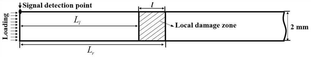
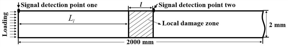
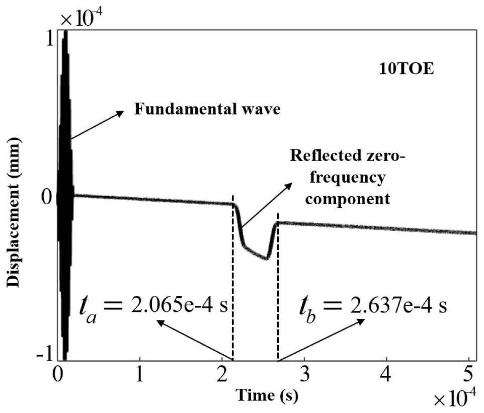
[0034] Such as figure 1 Shown, L l The distance from the left boundary of the local damage to the signal excitation point, v is the fundamental wave phase velocity, v 0 is the zero-frequency phase velocity, t a is the arrival time of the zero-frequency signal received by the signal receiving point (also the signal transmitting point), there is

[0035]

[0036] L r is the distance from the right boundary of the local damage to the signal excitation, t l is the departure and end time of the zero-frequency signal received by the signal receiving point (also the signal transmitting point), Δt is the width of the zero-frequency signal generated in the local damage area, and

[0037]

[0038] The width of the local damage area is

[0039] l=L r -L l (3)

[0040] According to the inventors in the document "SUN X Q, LIU H J, ZHAO Y X, et al. The zero-frequency component of bulk waves in solids with randomly distributed micro-cracks [J]. Ultrasonics, 2020, 107: 106172."...

Embodiment 2

[0056] The difference between this embodiment and Embodiment 1 is that the ultrasonic probe in this embodiment (mainly referring to the receiving point) includes: a housing 1, a CMUT sheet 4, an acoustic lens 3 and a controller; the CMUT sheet 4 includes multiple a CMUT element; the acoustic lens 3 is located on the surface of the CMUT sheet 4; the bottom surface of the CMUT sheet 4 is provided with a liner layer 7, the liner layer 7 is bonded to the CMUT sheet 4, and the liner layer 7 and the acoustic lens 3 are respectively Located at the top and bottom of the CMUT sheet 4; the CMUT sheet 4 is connected to the flexible substrate 2 through a wire; the flexible substrate 2 is electrically connected to the controller (the flexible substrate 2 is also connected to the controller with an external power lamp and other equipment); the housing 1 is provided with a piezoelectric ceramic sheet 5, and the piezoelectric ceramic sheet 5 is provided with an electrode 6 with opposite polari...


PUM


Abstract

The invention belongs to the field of plate wave early-stage damage nondestructive testing, and particularly relates to a damage positioning imaging method and system based on a nonlinear Lamb wave zero-frequency component, and the method specifically comprises the steps: 1, preparing a model to be detected; 2, transmitting a fundamental wave at a signal excitation point of the model, receiving a zero-frequency signal at the damaged position of the model by a signal receiving point, and obtaining a boundary point at the damaged position of the model; 3, signal excitation and signal receiving are carried out at multiple positions on the model, and a boundary dot matrix is obtained; and 4, performing model damage position positioning imaging according to the boundary dot matrix. The boundary of the material damage is determined by utilizing the high reflection characteristic of zero frequency to the early local damage of the material, so that the position of the material damage is positioned and imaged, the positioning method is simple and efficient, the detection of the early local damage can be as simple as the detection of the macroscopic damage (such as local 1cm cracks) of the material by utilizing linear fundamental waves, and the detection accuracy is high. And related bottlenecks of mixed wave and second harmonic technologies are overcome.

Description

technical field [0001] The invention belongs to the field of plate wave early damage detection, and in particular relates to a damage location imaging method and system based on a nonlinear Lamb wave zero-frequency component. Background technique [0002] The plate and shell structure has excellent performance and is widely used in all walks of life. These plate and shell structural materials will be more or less affected by stress, high temperature, high pressure and corrosion during use, and are very prone to damage such as fatigue, plasticity, corrosion and creep, which will gradually degrade the performance of the plate and cause an explosion. Safety accidents such as breakage, breakage and leakage of hazardous substances threaten the operation of equipment and the safety of personnel's lives and property, causing major social and economic losses. Therefore, it is a very important research topic in our country's national economic production and life to study powerful no...

Claims


Application Information

Patent Timeline
IPC IPC(8): G01N29/04
CPCG01N29/041G01N2291/023Y02T90/00
Inventor 孙晓强
Owner CHONGQING IND POLYTECHNIC COLLEGE
Why Eureka
Try Eureka