Viewing deck optimal floor and view angle determination method based on sight line analysis

A determination method and viewing platform technology, applied in the direction of instruments, geometric CAD, design optimization/simulation, etc., can solve the problems of low accuracy and large impact of accuracy, and achieve the goal of meeting precise positioning and improving determination accuracy and efficiency Effect

Pending Publication Date: 2022-05-06
CHINA MCC17 GRP
View PDF0 Cites 0 Cited by
  • Summary
  • Abstract
  • Description
  • Claims
  • Application Information

AI Technical Summary

Problems solved by technology

[0005] The purpose of the present invention is to solve the problem that the accuracy of the traditional building viewing optimal floor and viewing angle positioning method is greatly affected by human subjective factors, and the accuracy is not high, and provides a viewing platform optimal floor based on line of sight analysis and the way to determine the angle of view

Method used


Image

  • Viewing deck optimal floor and view angle determination method based on sight line analysis
  • Viewing deck optimal floor and view angle determination method based on sight line analysis
  • Viewing deck optimal floor and view angle determination method based on sight line analysis

Examples


Embodiment Construction

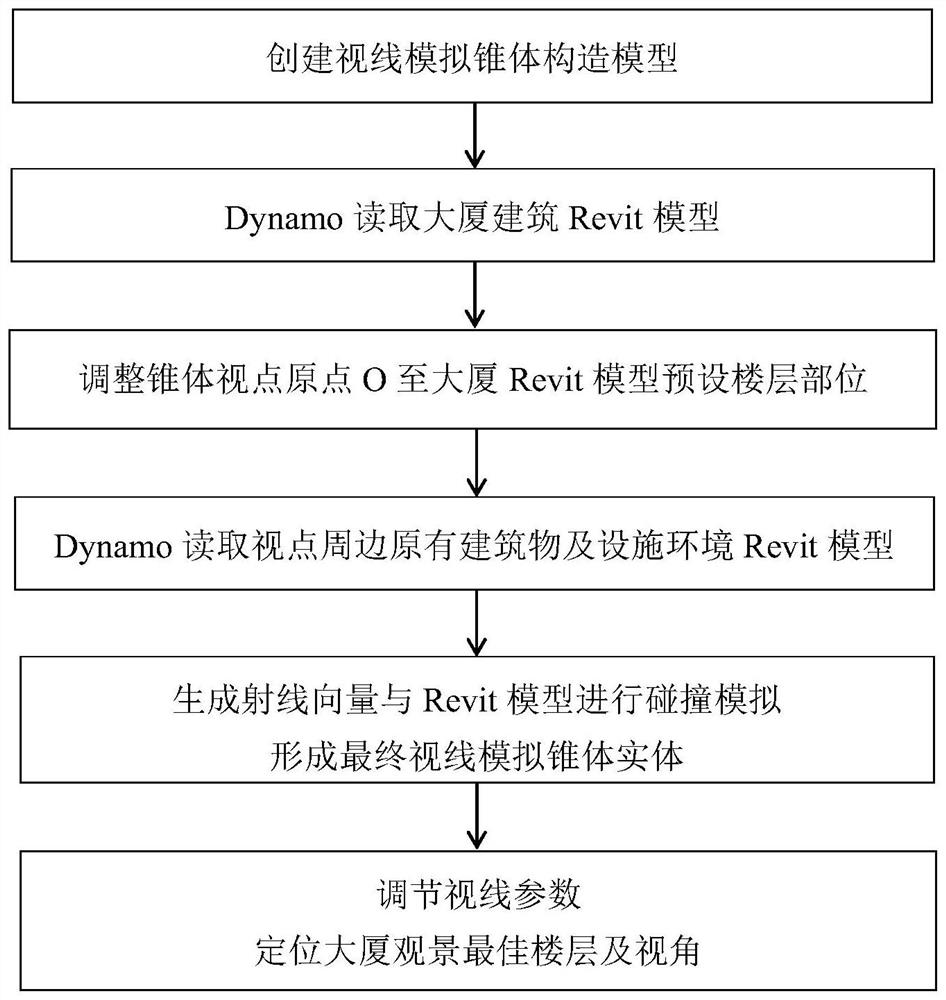
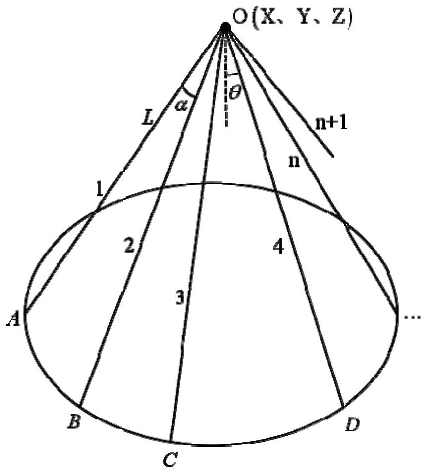
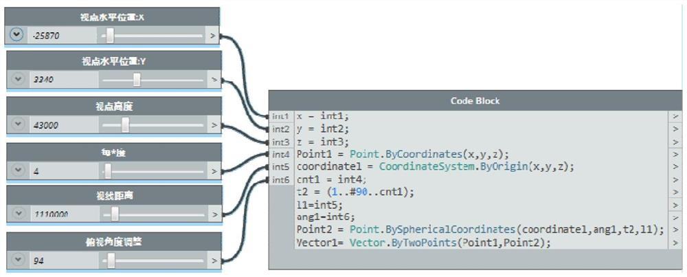
[0042] When using traditional design experience in the existing technology to determine the best floor and viewing angle of the building, the accuracy is greatly affected by human subjective factors. The selected floor cannot fully consider the relationship between the building and the surrounding environment, regional culture, and local culture. The effect of landscape and architectural aesthetics makes it difficult to guarantee the positioning accuracy. The present invention uses Dynamo visual programming to construct a sight simulation cone, combined with the Revit 3D model, and obtains the best floor for viewing the building by directly adjusting the line of sight parameters in Revit. Accurate predictive parametric models of perspective. By adopting the prediction model of the present invention, the precise positioning of the best floor and viewing angle of the building can be quickly realized.

[0043] combine Figure 1-10 , the present invention's viewing platform optim...


PUM


Abstract

The invention discloses a sight analysis-based method for determining an optimal floor and a visual angle of a viewing platform, and belongs to the technical field of positioning. According to the method, a sight line simulation cone is constructed through Dynamo visual programming, and a Revit three-dimensional model is combined, so that an accurate prediction model capable of directly adjusting sight line parameters in three-dimensional modeling software to position the optimal building viewing floor and view angle is obtained; and then, by applying the model, according to relevant parameter information of a designed mansion building and surrounding original buildings and facility environments, sight line parameters are modified, and the optimal floor and view angle of the viewing platform can be obtained. By adopting the technical scheme of the invention, the problems that the interference of external environmental factors is not fully considered, the influence of human subjective factors is large and the accuracy is not enough when an architect designs and positions the optimal viewing floor and viewing angle can be solved, and a parameterized prediction model is constructed, so that the method is rapid and efficient, and the design requirements of the architect are effectively met.

Description

technical field [0001] The invention belongs to the technical field of positioning, and more specifically relates to a method for determining the optimal floor and viewing angle of a viewing platform based on line-of-sight analysis. Background technique [0002] The viewing platform is a purely natural stop without any artificial carving or a purely artificial building or structure set up at a specific location. It is mainly an activity place for observing and enjoying the scenery. In recent years, with the rapid rise of high-rise buildings in the city, especially as a landmark building to display urban culture and urban heritage, the observation deck of the building has now become a beautiful new landscape. [0003] With the acceleration of the pace of urban life and the increasing pressure of work, the viewing floor of the building has become one of the iconic designs of humanized office space. For the staff, the viewing floor of the building can well relieve the tension a...

Claims


Application Information

Patent Timeline
Patent Type & Authority Applications(China)
IPC IPC(8): G06F30/13G06F30/20G06T17/00
CPCG06F30/13G06T17/00G06F30/20
Inventor 程安春李岱巍陈祥宇刘奇奇金仁才钱元弟
Owner CHINA MCC17 GRP
Why Eureka
Try Eureka