
Plug and plug assembly

A technology of plugs and plug shells, which is applied in the direction of electrical components, parts of connecting devices, fixed/insulated contact components, etc., can solve the problems of signal shielding effect and poor shielding continuity, and achieve the effect of improving the shielding effect

Pending Publication Date: 2022-05-06
CHINA AVIATION OPTICAL-ELECTRICAL TECH CO LTD
View PDF11 Cites 0 Cited by
  • Summary
  • Abstract
  • Description
  • Claims
  • Application Information

AI Technical Summary

Problems solved by technology

[0005] The purpose of the present invention is to provide a plug to solve the technical problem of poor signal shielding effect and shielding continuity during signal transmission due to the absence of a conductive connection structure between the plug shield and the socket shield in the prior art plug structure Correspondingly, the object of the present invention is also to provide a plug assembly to solve the problem of signal shielding effect and shielding continuity in the signal transmission process caused by the absence of a conductive communication structure between the plug shield and the socket shield in the prior art plug assembly Poor technical issues

Method used


Image

  • Plug and plug assembly
  • Plug and plug assembly
  • Plug and plug assembly

Examples


specific Embodiment 1

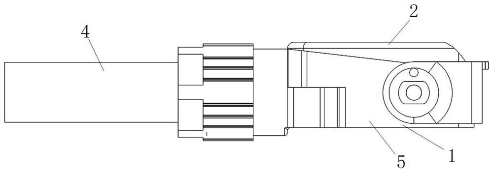
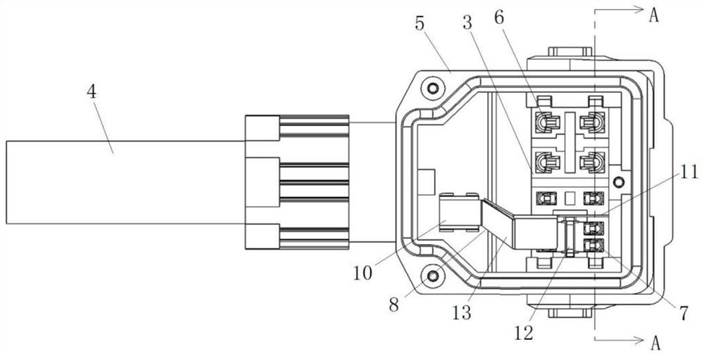
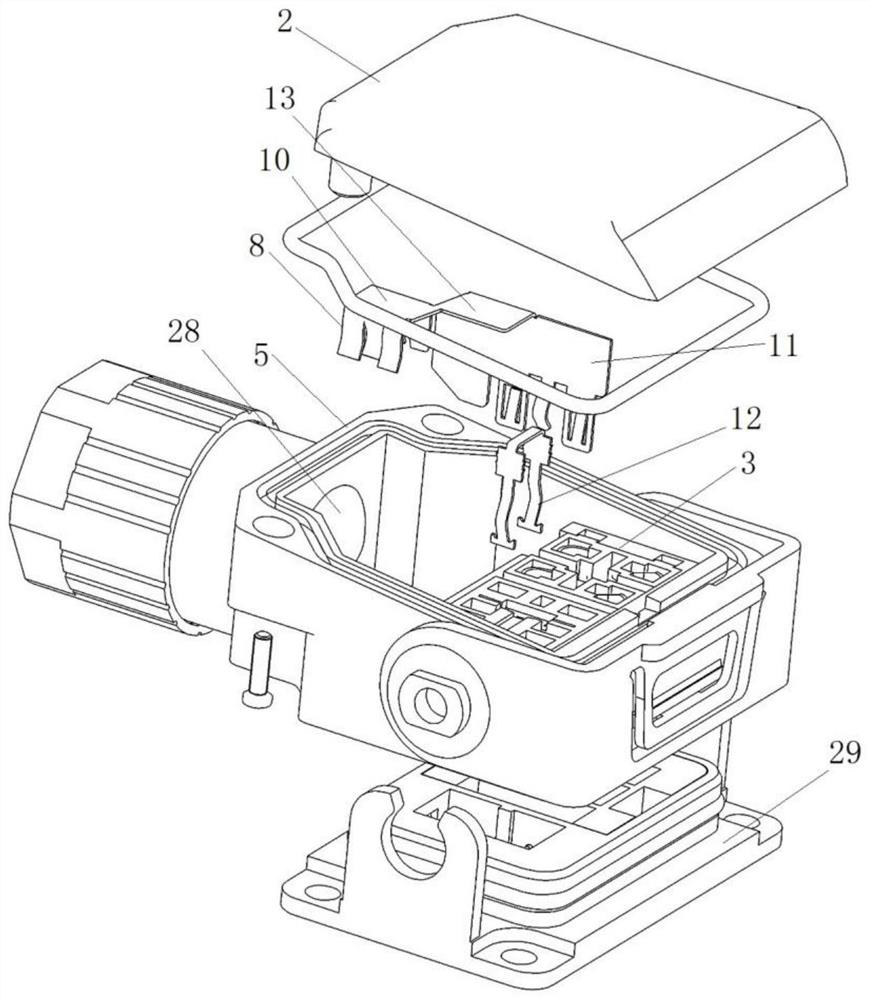
[0079] Such as figure 1 and figure 2 As shown, the plug assembly includes a plug and a cable 4, the plug includes a plug housing 1, the plug housing 1 has an inlet channel for the cable 4 to extend into the plug housing 1, and the cable 4 includes a signal harness and a power harness. Such as figure 2 , image 3 and Figure 6 As shown, the plug housing 1 includes a bottom case 5 and an upper cover 2 detachably fixed on the bottom case 5 by screws, as figure 1 and Figure 7 As shown, the upper cover 2 and the bottom case 5 are arranged in the up-down direction, and the plug also includes an insulator 3. After the upper cover 2 is opened, the insulator 3 exposes the bottom case 5, and the bottom case 5 has an insulator installation hole extending in the up-down direction. The insulator 3 is plugged and fitted with the bottom shell 5 from top to bottom, and the lower end of the insulator 3 forms a plug-in end for plugging into the socket. The upper stop plane, the stop pl...

specific Embodiment 2

[0093] The difference from the specific embodiment 1 is that the isolating part and the inserting part are integrated, no slot is provided on the insulator, the cantilever arm on the isolating part is fitted with the T-shaped slot, and the cantilever arm includes a The overhanging section also includes a vertical section located at the overhanging end of the overhanging section and perpendicular to the insertion direction. The vertical section guides and cooperates with the groove wall of the T-shaped slot so that the vertical section forms a guide. The part arched out of the notch of the socket forms the contact part of the socket, which is electrically connected with the socket housing when the plug and the socket are mated.

specific Embodiment 3

[0095] The difference from the specific embodiment 1 is that no slot is provided on the insulator, no cantilever arm is provided on the isolation part, and the main body of the isolation part is provided with a pin extending toward the signal contact installation area at the middle position of the two isolation cantilever arms. part, which is press-fitted with the bottom wall of the U-shaped structure of the insertion part in the insertion direction after the isolation part is positioned and installed, so as to realize the conductive communication between the isolation part and the insertion part.


PUM


Abstract

The invention relates to the technical field of connectors, in particular to a plug and a plug assembly. The plug assembly comprises a plug, a signal wire harness and a power wire harness, the plug comprises a plug shell and an insulator, the plug further comprises a plug shielding piece, the plug shielding piece is provided with a cable shielding part and a plug-in mounting part, the cable shielding part is arranged on a shielding layer of the signal wire harness and is in conductive communication with the shielding layer, and the plug-in mounting part is plugged in the insulator. When the plug is in plug-in fit with the socket, the plug is conductively communicated with the socket shielding structure. The plug shielding piece is in conductive communication with the shielding layer through the cable shielding part and is in conductive communication with the socket shielding through the inserting part, so that conductive communication of plug shielding, cable shielding and socket shielding is achieved, and the signal shielding effect and the signal shielding continuity in the signal transmission process are improved.

Description

technical field [0001] The invention relates to the technical field of connectors, in particular to a plug and a plug assembly. Background technique [0002] Most of the existing servo motors use a single-wire interface, that is, a set of interface connectors are used. The plug is provided with an incoming line channel for the cable to enter. The insertion direction of the plug and the socket is perpendicular to the extension direction of the incoming line channel. The plug connected with the cable is inserted into the socket installed on the motor to realize power supply and signal transmission of the motor. [0003] In order to prevent signal interference, signal transmission lines need to be shielded. Signal shielding includes cable shielding, plug shielding and socket shielding. Cable shielding is the shielding layer wrapped on the signal harness. Plug shielding is a plug shielding structure that isolates power contacts from signal contacts. Socket shielding is set in t...

Claims


Application Information

Patent Timeline
Patent Type & Authority Applications(China)
IPC IPC(8): H01R13/648H01R13/40H01R13/502
CPCH01R13/648H01R13/40H01R13/502
Inventor 赵海深曹兴朱磊杨国刚武学顺
Owner CHINA AVIATION OPTICAL-ELECTRICAL TECH CO LTD
Learn More