Cleaning device for dialysis equipment

A cleaning device and equipment technology, applied in the field of hemodialysis machines, can solve problems such as cross-infection, low efficiency, and unclean wiping, and achieve the effect of convenient centralized processing and improved efficiency

Active Publication Date: 2022-05-10
浦江县人民医院
View PDF9 Cites 0 Cited by
  • Summary
  • Abstract
  • Description
  • Claims
  • Application Information

AI Technical Summary

Problems solved by technology

[0005] In order to make up for the deficiencies of the existing technology, the hemodialysis machine needs to be wiped and disinfected with a sterile cloth in time after use, so as to avoid cross-infection in the next use, while the traditional disinfection method needs to be manually wiped slowly with a sterile cloth , this disinfection and cleaning method is inefficient, and it is very easy to have the problem that the details are not wiped, resulting in unclean wiping. The present invention proposes a cleaning device for dialysis equipment

Method used


Image

  • Cleaning device for dialysis equipment
  • Cleaning device for dialysis equipment
  • Cleaning device for dialysis equipment

Examples


Embodiment 1

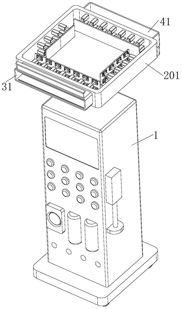
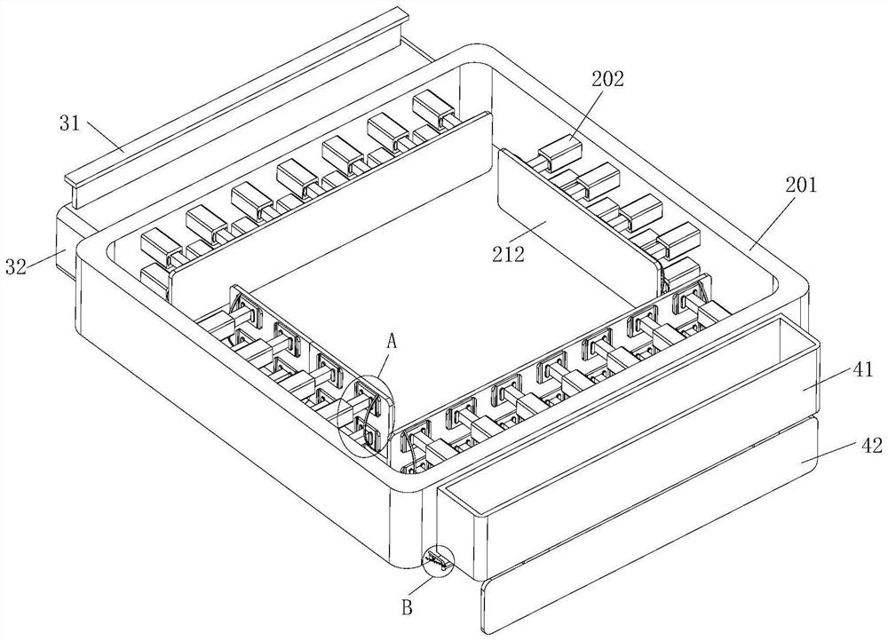
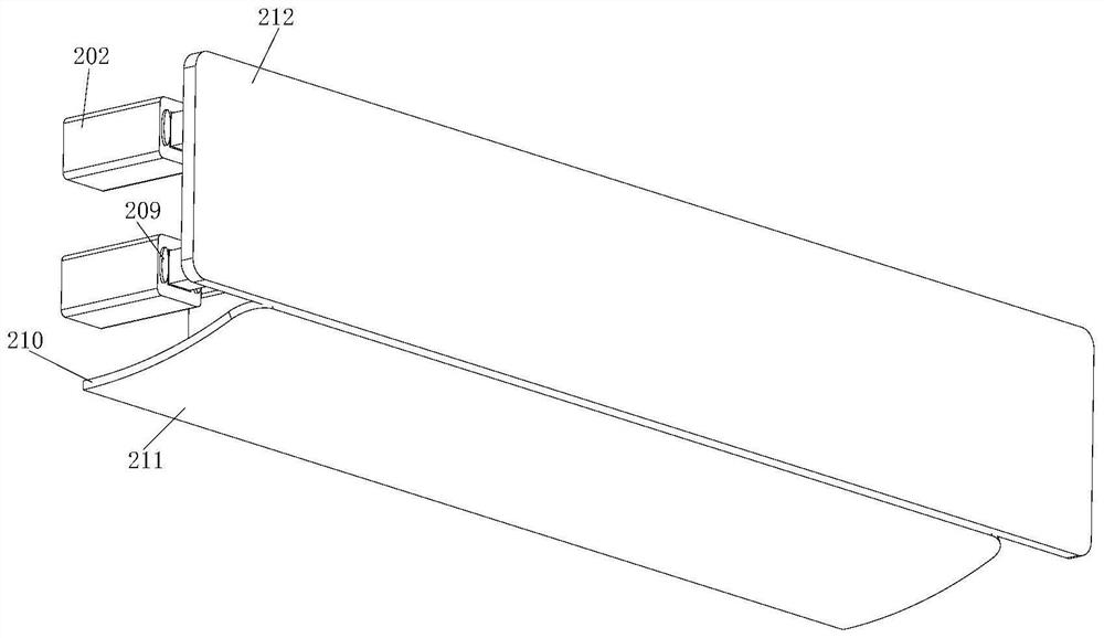
[0029] see Figure 1-6 As shown, a dialysis equipment cleaning device includes a hemodialysis machine 1, a cleaning frame 201 and a connecting column 202; the top of the hemodialysis machine 1 is provided with a cleaning frame 201, and the inner wall of the cleaning frame 201 is fixedly equipped with a connecting column 202, the inside of the connecting column 202 is slidably connected with a sliding column 203, the inside of the connecting column 202 is fixedly installed with a first spring 204, the other end of the first spring 204 is fixedly installed with the sliding column 203, and the sliding One end of the column 203 away from the first spring 204 is fixedly equipped with a rectangular plate 205, and the side of the rectangular plate 205 away from the sliding column 203 is provided with a sterile cotton cloth 212; At this time, put the cleaning frame 201 on the upper end of the hemodialysis machine 1, and then slide the cleaning frame 201 down the hemodialysis machine 1...

Embodiment 2

[0038] see Figure 7 As shown in Comparative Example 1, as another embodiment of the present invention, handles 5 are fixedly installed on both sides of the cleaning frame 201, and the inner wall of the handle 5 is provided with four grooves 6; when working, when When the cleaning frame 201 needs to be moved, by gripping the handle 5, the four grooves 6 on the inner wall of the handle 5 just fit the fingers, so that it is convenient to grip the handle 5, and then the handle 5 is moved with the cleaning frame 201.

[0039] Working principle, by pulling the elastic bandage 206 on the sterile cotton cloth 212, the space between the elastic bandage 206 and the sterile cotton cloth 212 becomes larger, and the sterile cotton cloth 212 is placed on the rectangular plate 205, so that the elastic bandage 206 is inserted into the In the slot 207, the sterile cotton cloth 212 and the fast rectangular plate 205 are then fixed. At this time, the cleaning frame 201 is placed on the upper en...


PUM


Abstract

The invention belongs to the field of hemodialysis machines, and particularly relates to a dialysis equipment cleaning device which comprises a hemodialysis machine, a cleaning frame and a connecting column. A cleaning frame is arranged at the top of the hemodialysis machine, a connecting column is fixedly installed on the inner wall of the cleaning frame, a sliding column is slidably connected into the connecting column, a first spring is fixedly installed in the connecting column, and the other end of the first spring and the sliding column are fixedly installed. A rectangular plate extrudes a sliding column and a first spring, so that the sliding column can drive the rectangular plate and the sterilized cotton cloth to move and further adapt to a bulge of the hemodialysis machine, the cleaning frame can slide at will, and after the rectangular plate crosses the bulge of the hemodialysis machine, the first spring drives the sliding column to reset; therefore, all-directional wiping and cleaning of the hemodialysis machine are achieved, manual wiping of the hemodialysis machine is not needed, and the cleaning efficiency is greatly improved.

Description

technical field [0001] The invention relates to the field of hemodialysis machines, in particular to a cleaning device for dialysis equipment. Background technique [0002] A hemodialysis machine removes some waste from the blood through a semipermeable membrane. [0003] The hemodialysis machine is divided into two parts: the blood monitoring alarm system and the dialysate supply system. Its working principle is: the concentrated solution for dialysis and the water for dialysis are prepared through the dialysate supply system to prepare qualified dialysate, which passes through the hemodialyzer and communicates with the blood monitoring alarm. The patient's blood drawn from the system undergoes solute diffusion, osmosis, and ultrafiltration. [0004] After the hemodialysis machine is used, it needs to be wiped and disinfected with a sterile cloth in time to avoid cross-infection when it is used next time. The traditional disinfection method needs to be wiped slowly with a ...

Claims


Application Information

Patent Timeline
Patent Type & Authority Applications(China)
IPC IPC(8): B08B1/00B08B13/00A61L2/00
CPCB08B1/006B08B1/008B08B13/00A61L2/00
Inventor 童仙女
Owner 浦江县人民医院
Why Eureka
Try Eureka