Adjusting assembly, reaction cavity device and microwave plasma vapor deposition system
A technology for adjusting components and reaction chambers, applied in gaseous chemical plating, metal material coating process, coating, etc., can solve problems such as difficulty in adapting to the parts to be coated, fixed size, etc., and achieve the effect of increasing the scope of use
- Summary
- Abstract
- Description
- Claims
- Application Information
AI Technical Summary
Problems solved by technology
Method used
Image

Examples
Embodiment 1
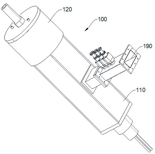
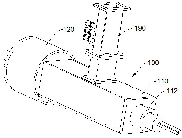
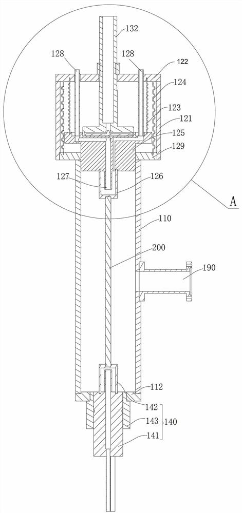
[0039] Please refer to Figure 1-Figure 3 , the present embodiment provides a reaction chamber device 100 , which includes a reaction chamber housing 110 , an adjustment assembly 120 is provided at one end of the reaction chamber housing 110 and a blocking assembly 140 is provided at the other end. The adjusting assembly 120 is used to adjust the length of the inner space of the reaction chamber housing 110 , and the blocking assembly 140 is detachably connected to the reaction chamber housing 110 , so as to facilitate putting the rod 200 to be coated into the reaction chamber housing 110 .
[0040] Specifically, the reaction chamber housing 110 is a cuboid cavity structure formed by connecting four rectangular steel plates; a rectangular through hole is provided in the middle of one of the steel plates. A rectangular tubular microwave transmission component 190 is disposed at the rectangular through hole, and the microwave transmission component 190 is connected to the reacti...
Embodiment 2
[0057] Please refer to Figure 6 and Figure 7 , this embodiment provides another reaction chamber device 100, which differs from the reaction chamber device 100 in Embodiment 1 in that both ends of the reaction chamber housing 110 of the reaction chamber device 100 in this embodiment are provided with adjustment components 120.
[0058] The adjustment assembly 120 at one end of the above-mentioned reaction chamber device 100 has the same structure as that in Embodiment 1, and an air intake assembly 130 of the same structure is also provided; the middle part of the adjustment assembly 120 at the other end is provided with a lifting rod 180, and the lifting rod 180 can be moved from The adjustment assembly 120 is disassembled, so as to facilitate the loading and unloading of the rod 200 to be coated. For ease of description, the adjustment assembly 120 provided with the lifting rod 180 is referred to as the second adjustment assembly 120 , and the other adjustment assembly 12...
Embodiment 3
[0063] This embodiment provides a microwave plasma vapor deposition system, which includes a microwave source, a microwave transmission component, and the reaction chamber device 100 in Embodiment 1 or 2; the microwave source is connected to the microwave transmission component 190 through the microwave transmission component, so that The microwave can enter the reaction cavity through the microwave transmission component 190 .
[0064] Since both the microwave source and the microwave transmission component can adopt existing structures, they will not be described in detail.
PUM
 Abstract
Description
Claims
Application Information
 - Generate Ideas
- Intellectual Property
- Life Sciences
- Materials
- Tech Scout
- Unparalleled Data Quality
- Higher Quality Content
- 60% Fewer Hallucinations
Browse by: Latest US Patents, China's latest patents, Technical Efficacy Thesaurus, Application Domain, Technology Topic, Popular Technical Reports.
© 2025 PatSnap. All rights reserved.Legal|Privacy policy|Modern Slavery Act Transparency Statement|Sitemap|About US| Contact US: help@patsnap.com