
Power supply circuit and camera testing device

A technology of power supply circuit and power supply module, which is applied in the direction of program control, instrument, computer control, etc., to achieve the effect of satisfying the current test accuracy and solving the power supply voltage accuracy

Pending Publication Date: 2022-05-10
SHENZHEN CZTEK
View PDF4 Cites 0 Cited by
  • Summary
  • Abstract
  • Description
  • Claims
  • Application Information

AI Technical Summary

Problems solved by technology

[0005] The main purpose of the present invention is to provide a power supply circuit and a camera test device, aiming at solving the premise of power supply voltage accuracy and current test accuracy, so that the test system can simultaneously cover high dynamic range voltage and high dynamic range current

Method used


Image

  • Power supply circuit and camera testing device
  • Power supply circuit and camera testing device
  • Power supply circuit and camera testing device

Examples


Embodiment Construction

[0026] Embodiments of the present application are described in detail below, examples of which are shown in the drawings, wherein the same or similar reference numerals denote the same or similar elements or elements having the same or similar functions throughout. The embodiments described below by referring to the figures are exemplary only for explaining the present application, and are not construed as limiting the present application.

[0027] Those skilled in the art will understand that unless otherwise stated, the singular forms "a", "an", "said" and "the" used herein may also include plural forms. It should be further understood that the word "comprising" used in the specification of the present application refers to the presence of the features, integers, steps, operations, elements and / or components, but does not exclude the presence or addition of one or more other features, Integers, steps, operations, elements, components, and / or groups thereof. It will be under...


PUM


Abstract

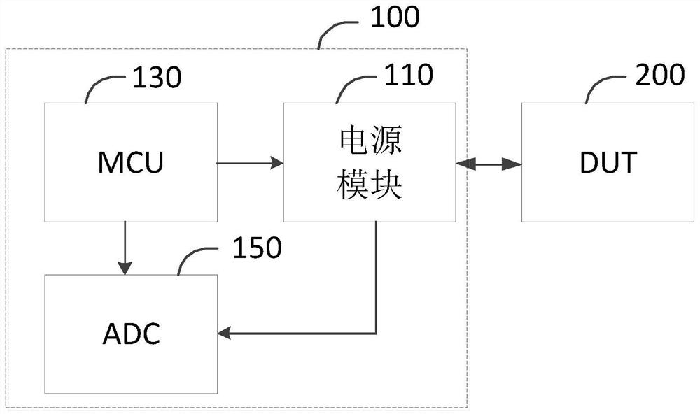
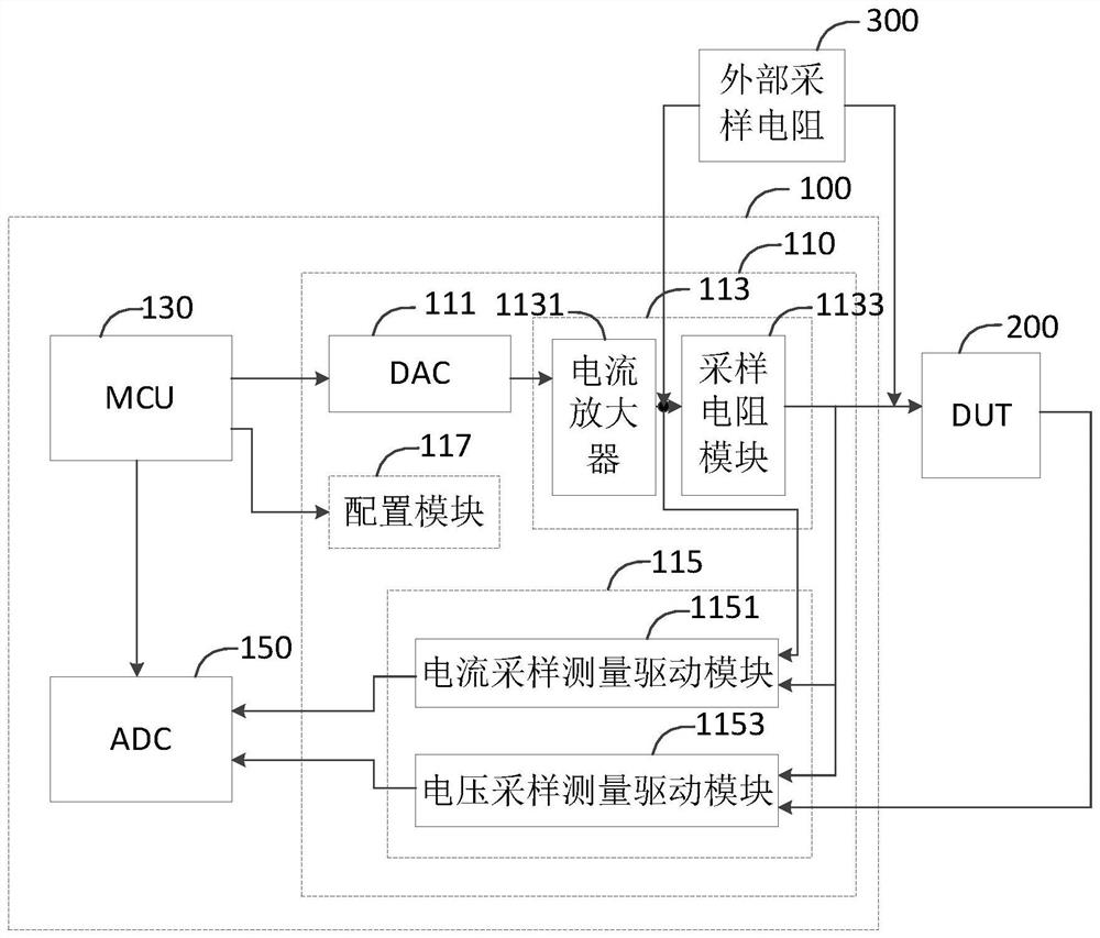
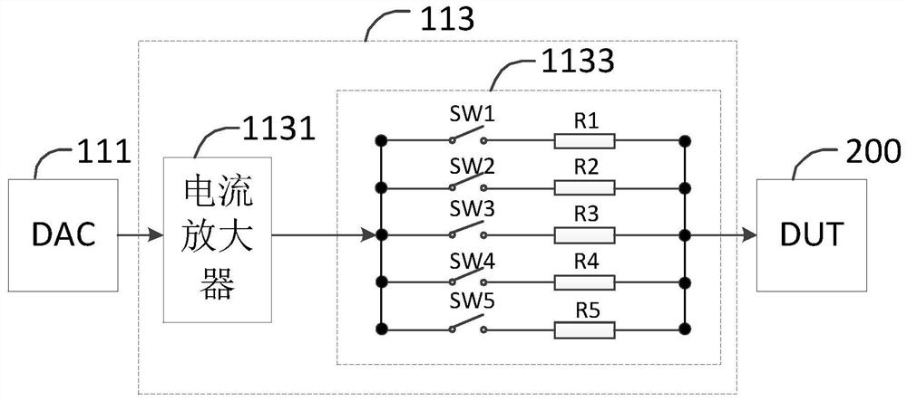
The invention discloses a power supply circuit and a camera testing device, and relates to the field of industrial general testing equipment.The power supply circuit comprises a micro control unit (MCU), an analog-to-digital conversion (ADC) module and at least one power supply module connected with a device to be tested (DUT), the MCU controls the power supply module to output a power supply signal to the connected DUT, and the MCU controls the power supply module to output the power supply signal to the device to be tested. The detected current value and / or voltage value of the DUT are / is output to the ADC module; the ADC module performs analog-to-digital conversion on the current value and / or the voltage value of the DUT and then feeds back the current value and / or the voltage value to the MCU; and the MCU controls the power supply module to adaptively adjust the output power supply signal according to the feedback current value and / or voltage value, thereby solving the problems of poor power supply precision, poor stability and poor universality in the camera test device in the prior art, realizing the camera test device, and improving the test efficiency. The system meets the requirements of high voltage dynamic range and high current dynamic range while solving the problems of power supply voltage precision and current test precision.

Description

technical field [0001] The application relates to the field of industrial general testing equipment, in particular to a power supply circuit and a camera testing device. Background technique [0002] In industrial general-purpose test equipment, the equipment must be compatible with various test loads, and the power supply voltage, industrial current, standby current, and protection current of each device under test (DUT) may be inconsistent. The power supply voltage ranges from a few tenths of V to more than a dozen V, and the current ranges from μA level to A level. The dynamic range of voltage and current is very large, and the accuracy requirements are very high. [0003] The digital power supply in the current test equipment either uses a power management unit (PMU) chip or a discrete device solution. In the solution using the PMU chip, it is difficult for the general adjustable power supply voltage and current sampling measurement drive module to cover high dynamic ran...

Claims


Application Information

Patent Timeline
Patent Type & Authority Applications(China)
IPC IPC(8): G05B19/042
CPCG05B19/0423G05B2219/24036
Inventor 谭湘王林旺范艳根
Owner SHENZHEN CZTEK
Learn More