
Hydrogen refueling station hydrogen energy filling control method and device, computer equipment and storage medium

A hydrogen refueling station and tube loading technology, which is applied in the field of hydrogen refueling stations, can solve the problems of poor filling effect, the filling speed cannot reach the optimal speed, and the order of filling cannot be determined, so as to ensure legality and improve Filling rate, effect of improving filling effect

Active Publication Date: 2022-05-10
内蒙古中科装备有限公司 +1
View PDF3 Cites 0 Cited by
  • Summary
  • Abstract
  • Description
  • Claims
  • Application Information

AI Technical Summary

Problems solved by technology

Fuel cell vehicles generally use hydrogen energy. At present, during the filling process of different hydrogen refueling stations, the filling temperature of hydrogen is related to the pressure value of the hydrogen storage bottle. The current control method is to artificially set a filling temperature for all Most automobile hydrogen storage bottles are filled with hydrogen at a uniform filling temperature, which leads to the fact that the filling speed cannot reach the optimal speed, and the filling process cannot form an optimal filling plan, that is, the filling sequence cannot be determined, thus Leading to poor filling effect when multiple car hydrogen storage bottles line up for filling

Method used

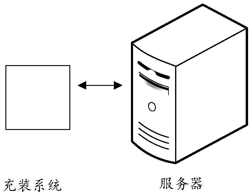

Image

  • Hydrogen refueling station hydrogen energy filling control method and device, computer equipment and storage medium
  • Hydrogen refueling station hydrogen energy filling control method and device, computer equipment and storage medium
  • Hydrogen refueling station hydrogen energy filling control method and device, computer equipment and storage medium

Examples


Embodiment Construction

[0059] The following will clearly and completely describe the technical solutions in the embodiments of the present invention with reference to the accompanying drawings in the embodiments of the present invention. Obviously, the described embodiments are some of the embodiments of the present invention, but not all of them. Based on the embodiments of the present invention, all other embodiments obtained by persons of ordinary skill in the art without making creative efforts belong to the protection scope of the present invention.

[0060] It should be understood that when used in this specification and the appended claims, the terms "comprising" and "comprises" indicate the presence of described features, integers, steps, operations, elements and / or components, but do not exclude one or Presence or addition of multiple other features, integers, steps, operations, elements, components and / or collections thereof.

[0061] It should also be understood that the terminology used ...


PUM


Abstract

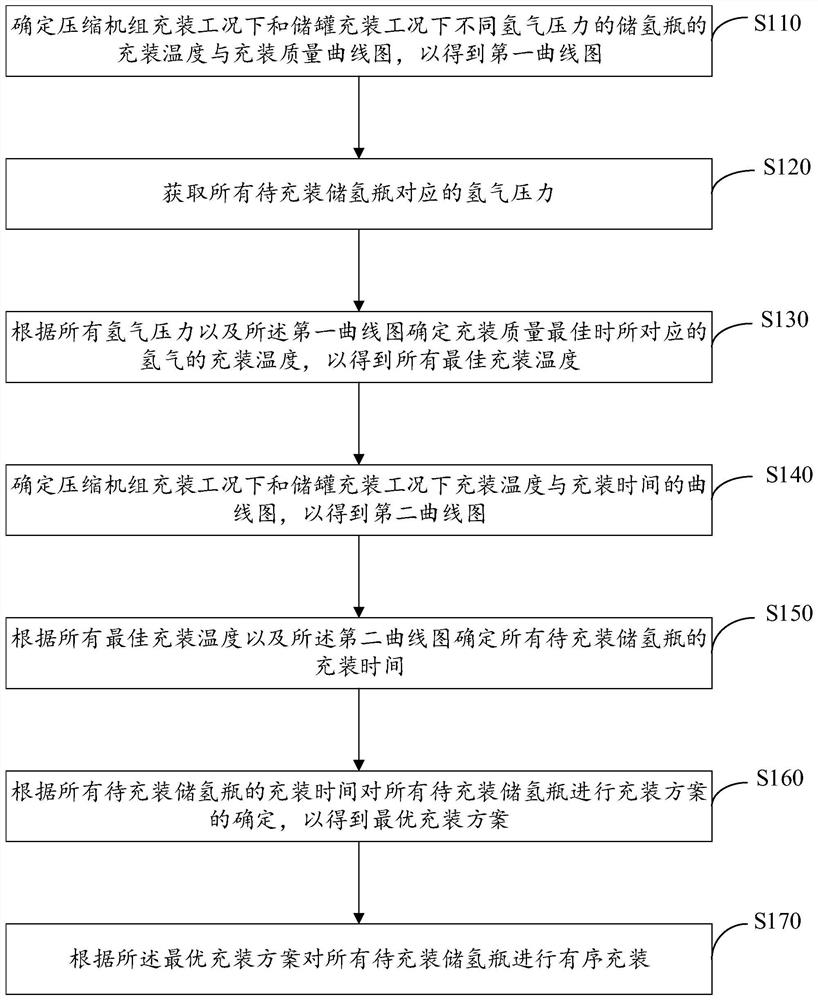
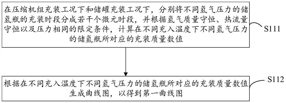
The embodiment of the invention discloses a hydrogen refueling station hydrogen energy filling control method and device, computer equipment and a storage medium. The method comprises the following steps: determining a charging temperature and charging quality curve graph of hydrogen storage cylinders with different hydrogen pressures under a compressor unit charging working condition and a storage tank charging working condition; hydrogen pressure corresponding to all the hydrogen storage cylinders to be filled is obtained; the corresponding hydrogen filling temperature when the filling quality is optimal is determined, so that all the optimal filling temperatures are obtained; a curve graph of the filling temperature and the filling time under the compressor unit filling working condition and the storage tank filling working condition is determined; the filling time of all the hydrogen storage bottles to be filled is determined; the filling scheme of all the hydrogen storage bottles to be filled is determined, so that the optimal filling scheme is obtained; and all the hydrogen storage bottles to be filled are filled in order. By implementing the method provided by the embodiment of the invention, the filling temperature can be adjusted in real time according to the automobile hydrogen storage bottles with different pressures, so that the filling speed is increased, and the filling effect when a plurality of automobile hydrogen storage bottles are filled in line is improved.

Description

technical field [0001] The present invention relates to a hydrogen refueling station, and more specifically refers to a hydrogen refueling station hydrogen filling control method, device, computer equipment and storage medium. Background technique [0002] With the development of economy and technology, the excessive development and use of traditional industrial energy, carbon dioxide emissions are increasing, causing global warming, and now countries all over the world are working hard to reduce carbon emissions. Hydrogen energy is recognized as a clean energy source and is emerging as a low-carbon and zero-carbon energy source. Fuel cell vehicles generally use hydrogen energy. At present, during the filling process of different hydrogen refueling stations, the filling temperature of hydrogen is related to the pressure value of the hydrogen storage bottle. The current control method is to artificially set a filling temperature for all Most automobile hydrogen storage bottl...

Claims


Application Information

Patent Timeline
Patent Type & Authority Applications(China)
IPC IPC(8): G06Q10/06G06Q50/06
CPCG06Q10/06311G06Q10/06315G06Q10/0639G06Q50/06Y02E60/32
Inventor 周奕丰王军代新刘星
Owner 内蒙古中科装备有限公司
Learn More