Electronic fence based on tension
An electronic fence and tension technology, applied to electrical components, closed-circuit television systems, alarms that are straightened by breaking/disturbing ropes/metal wires, etc., can solve the problem that the alarm signal stays at the front end, cannot distinguish the alarm state, and cannot Determine problems such as intrusion to achieve technical defense, facilitate monitoring and evidence collection, and prevent alarms
- Summary
- Abstract
- Description
- Claims
- Application Information
AI Technical Summary
Problems solved by technology
Method used
Image
Examples
Embodiment 1
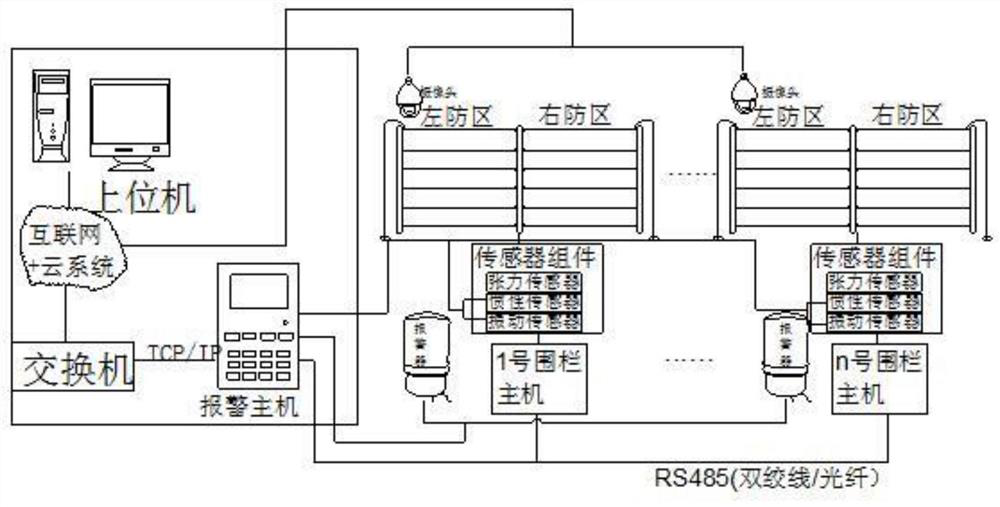
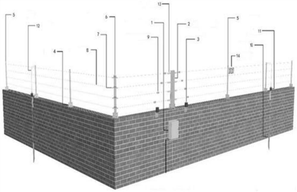
[0059] to combine figure 1 , a tension-based electronic fence comprising a fence, including a physical layer, a sensing layer, a control layer, and a network layer.
[0060] Among them, the physical layer includes tension fence unit, video linkage unit and alarm unit, such as Figure 6 , when it is detected that the fence unit has an intrusion abnormality, the alarm signal is transmitted to the video linkage unit through the serial port, and the video linkage unit performs command analysis according to the received serial port data, and then decides whether to start video acquisition. The tension fence unit and video The linkage units are all connected to the alarm unit.
[0061] The sensing layer, including the sensor components installed in the tension fence unit, detects the state of the fence unit in real time, and transmits the detected signal to the fence host 1 .
[0062] The control layer includes the fence host 1 located on the fence and the host computer for contro...
Embodiment 2
[0066] On the basis of embodiment 1, the described alarm unit includes an alarm host, an alarm module and an alarm 3, and the described alarm host receives monitoring data from the sensing layer, and connects the detection data to the host computer through the network layer, The alarm host analyzes and processes the monitoring data through the alarm module, and starts or closes the alarm 3 according to the processing result, and the alarm 3 is arranged on the fence, and the alarm module includes:
[0067] In the tension alarm module, if the detected tension is greater than a certain threshold for a period of time, it will be judged that there is a tension abnormality and an alarm will be issued; in the slack alarm module, if the detected tension is lower than a certain threshold for a period of time, it will be judged that there is a relaxation abnormality and an alarm will be issued. Alarm; open circuit alarm module, when there is a signal short circuit, it will judge that the...
Embodiment 3
[0072] On the basis of embodiment 1, described sensor assembly comprises:
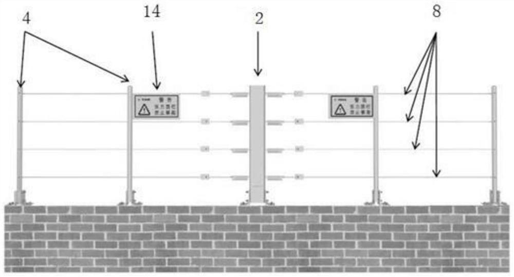
[0073] The tension sensor 15 is located in the control rod 2 and is connected to the corresponding tension cable 8 through the tension spring 13 to detect the tension change of the tension cable 8, and each tension cable 8 corresponds to a tension sensor 15;
[0074] Inertial sensors are laid on the fence in groups through tension cables 8 at intervals of 2-3 meters, and the intrusion signals are collected and input to the fence host 1 for analysis or directly input to the alarm host for analysis. The inertial sensors are installed in common defense zones Inside;
[0075] The vibration sensor is attached to the tension cable 8, senses the weak pressure and deformation transmitted from the surface of the tension cable 8, collects the intrusion signal and transmits it to the fence host 1 or directly inputs it to the alarm host for analysis, and the vibration sensor is installed In the key defense area, ...
PUM
 Abstract
Description
Claims
Application Information
 - R&D
- Intellectual Property
- Life Sciences
- Materials
- Tech Scout
- Unparalleled Data Quality
- Higher Quality Content
- 60% Fewer Hallucinations
Browse by: Latest US Patents, China's latest patents, Technical Efficacy Thesaurus, Application Domain, Technology Topic, Popular Technical Reports.
© 2025 PatSnap. All rights reserved.Legal|Privacy policy|Modern Slavery Act Transparency Statement|Sitemap|About US| Contact US: help@patsnap.com


