
Hydrogen fuel cell humidification system and humidification method

A fuel cell and humidification system technology, applied in fuel cells, circuits, electrical components, etc., can solve problems such as difficulty in ensuring the humidification effect of hydrogen, inability of gas to enter the catalytic layer, and inability to balance the moisture content of the proton exchange membrane.

Active Publication Date: 2022-05-10
京氢未来新能源科技(北京)有限公司
View PDF8 Cites 0 Cited by
  • Summary
  • Abstract
  • Description
  • Claims
  • Application Information

AI Technical Summary

Problems solved by technology

The working temperature of the fuel cell stack is about 80°C, so the proton exchange membrane inside the battery will greatly reduce the proton conductivity of the proton exchange membrane due to the evaporation of water, so that the internal resistance of the battery will increase, and the dry proton exchange membrane will also Irreversible degradation occurs, so it is necessary to ensure the wetting of the fuel cell membrane
On the other hand, when there is too much water inside the fuel cell, the proton exchange membrane electrode is submerged, so that the gas cannot enter the catalytic layer, which hinders the progress of the battery reaction. This phenomenon is called water flooding.
At present, it is still impossible to balance the moisture content of the proton exchange membrane, and the conventional hydrogen humidification is solved by additional water injection, which is easy to cause waste of water resources, and it is difficult to ensure the humidification effect of hydrogen

Method used

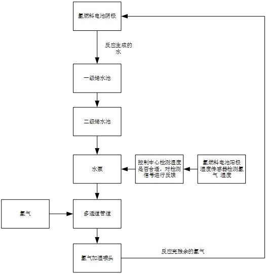

Image

  • Hydrogen fuel cell humidification system and humidification method
  • Hydrogen fuel cell humidification system and humidification method
  • Hydrogen fuel cell humidification system and humidification method

Examples


Embodiment Construction

[0028] It should be noted that the following detailed description is exemplary and intended to provide further explanation of the present invention. Unless defined otherwise, all technical and scientific terms used herein have the same meaning as commonly understood by one of ordinary skill in the art to which this invention belongs.

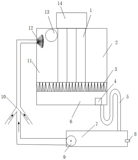
[0029] In the first aspect, the present invention provides a hydrogen fuel cell humidification system, including a hydrogen fuel cell, a filter screen, a primary water storage tank, a serpentine pipe and a secondary water storage tank, wherein,

[0030] The primary water storage tank is arranged under the hydrogen fuel cell, and both are sealed in the same housing, and the filter screen is arranged between the two, and an ultrasonic humidifier is arranged in the primary water storage tank;

[0031] The filter holes of the filter screen are rounded truncated;

[0032] The serpentine tube communicates between the bottom of the first-level water s...


PUM


Abstract

The hydrogen fuel cell humidification system comprises a hydrogen fuel cell, a filter screen, a primary water storage tank, a coiled pipe and a secondary water storage tank, the primary water storage tank is arranged below the hydrogen fuel cell, the primary water storage tank and the hydrogen fuel cell are sealed in the same shell, the filter screen is arranged between the primary water storage tank and the hydrogen fuel cell, and the coiled pipe is arranged in the secondary water storage tank. An ultrasonic humidifier is arranged in the primary water storage tank; the filter holes of the filter screen are inverted circular truncated cone-shaped; the coiled pipe is communicated between the bottom of the first-stage water storage tank and the second-stage water storage tank, and the highest point of the coiled pipe is higher than the set height of the bottom of the first-stage water storage tank. The automatic drainage of the hydrogen fuel cell and the automatic humidification of hydrogen entering the fuel cell can be realized, the oxidation-reduction reaction efficiency of the hydrogen fuel cell is promoted, and the efficient work of the hydrogen fuel cell is promoted.

Description

technical field [0001] The invention relates to the technical field of hydrogen fuel cells, in particular to a hydrogen fuel cell humidification system and a humidification method. Background technique [0002] The statements herein merely provide background information related to the present invention and do not necessarily constitute prior art. [0003] The working process of the hydrogen fuel cell is that hydrogen generates hydrogen ions and releases electrons under the action of the anode catalyst. The hydrogen ions pass through the proton exchange membrane to the cathode, and the electrons are collected by the current collecting plate and flow to the cathode from the external circuit; Under the action, it is reduced and combined with hydrogen ions and external circuit electrons to form water. The resulting water is generally discharged as wastewater. [0004] On the one hand, proton exchange membranes require water to ensure good proton conductivity. The working temp...

Claims


Application Information

Patent Timeline
IPC IPC(8): H01M8/04119
CPCH01M8/04126H01M8/04149Y02E60/50
Inventor 高志杰黄晓明苏洲陈中傲于立国李文晶
Owner 京氢未来新能源科技(北京)有限公司
Learn More