
High-speed low-power-consumption capacitive touch detection circuit, method and chip

A technology of capacitive touch and detection circuit, applied in capacitance measurement, measurement of resistance/reactance/impedance, electronic switches, etc., can solve the problems of increasing chip cost and power consumption, small touch difference, and high chip power consumption, so as to improve detection Speed ​​and detection accuracy, and the effect of reducing detection power consumption

Pending Publication Date: 2022-05-10
深圳市敏锐微电子有限公司
View PDF0 Cites 0 Cited by
  • Summary
  • Abstract
  • Description
  • Claims
  • Application Information

AI Technical Summary

Problems solved by technology

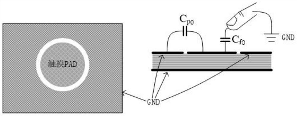
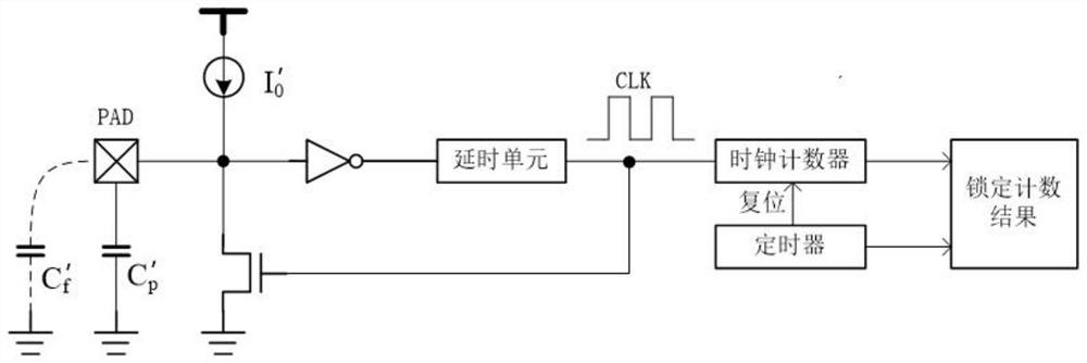
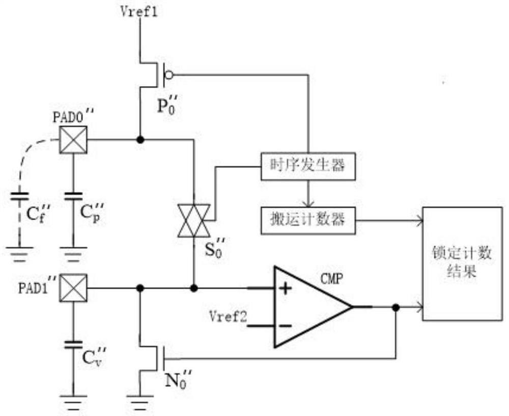
[0007] From the above two capacitive touch detection, due to C p0 about C f0 100 times that of the surrounding environment and noise, at this time the values ​​of Vth1 and Vth2 must be at least greater than 5. In order to obtain a stable touch value, the clock oscillation detection must oscillate at least 1000 clocks to obtain a reliable touch result. The same charge Handling detection also needs to reach more than 1000 times of handling
This makes the single detection cycle time longer, which will lead to the following disadvantages: (1) the touch module is in the working state for a long time, and in the same intermittent time, the power consumption of the chip is high; (2) it is not conducive to multi-channel detection , if there are many touch detection buttons, multiple touch detection modules are needed, thereby increasing the cost and power consumption of the chip; (3) because the difference generated by touch is small, it is difficult to realize multi-level intensity touch. The touch bar or sliding touch cannot achieve delicate effects

Method used


Image

  • High-speed low-power-consumption capacitive touch detection circuit, method and chip
  • High-speed low-power-consumption capacitive touch detection circuit, method and chip
  • High-speed low-power-consumption capacitive touch detection circuit, method and chip

Examples


Embodiment 1

[0046] Such as Figure 4 As shown, a high-speed and low-power capacitive touch detection circuit includes a touch module and a successive approximation module. The touch module includes a charging power module and a comparison trigger module. The charging power module is respectively connected to the input side of the comparison trigger module and an external touch PAD. The output side of the comparison trigger module is connected with the successive approximation module.

[0047] Such as Figure 5 As shown, the charging power supply module includes a first current source I1, a second current source I2, a third current source I3, and a fourth current source I4. The output terminal of the first current source I1 is connected in parallel with a first capacitor C1 and a first resistor R1. The first resistor R1 is connected in series between the first current source I1 and the second current source I2, the output terminal of the second current source I2 is connected in parallel w...

Embodiment 2

[0075] Such as Figure 10 As shown, a high-speed low-power capacitive touch detection method is based on the high-speed low-power capacitive touch detection circuit described in Embodiment 1. The method steps include:

[0076] S1: Perform successive approximation calculations in sequence according to the current control bits of the first current source to obtain an output current value of the first current source;

[0077] Specifically, successive approximation calculations are performed sequentially according to the current control bit of the first current source, and the number of calculations is determined by the current control bit width of the first current source, that is, starting from the highest bit of the current control bit of the first current source until the first current source The last bit of the current control bit ends. First, set the RST reset signal to 1 through the successive approximation module, so that the first NOMS transistor N1, the second NOMS tran...

Embodiment 3

[0103] A high-speed and low-power capacitive touch detection chip includes the above-mentioned high-speed low-power capacitive touch detection circuit.

[0104] The chips provided in the embodiments of the present invention are for brief description, and for those not mentioned in the embodiments, reference may be made to the corresponding content in the foregoing embodiments.

[0105] The invention adopts the method of successive approximation for capacitive touch detection, improves the detection speed and detection accuracy, reduces the detection power consumption, and realizes fast multi-channel and multiple detection at the same time, and can detect the touch intensity by configuring different touch thresholds, and also With touch slide detection function.


PUM


Abstract

The invention discloses a high-speed low-power-consumption capacitive touch detection circuit, method and chip, the circuit comprises a touch module and a successive approximation module, the touch module comprises a charging power supply module and a comparison trigger module, the charging power supply module is connected with the input side of the comparison trigger module and an external touch PAD, and the comparison trigger module is connected with the external touch PAD. And the output side of the comparison trigger module is connected with the successive approximation module. Capacitive touch detection is carried out in a successive approximation mode, the detection speed and the detection precision are improved, the detection power consumption is reduced, meanwhile, rapid multi-channel and multi-time detection is achieved, touch intensity detection can be carried out by configuring different touch threshold values, and the touch sliding detection function is further achieved.

Description

technical field [0001] The invention relates to the technical field of integrated circuits, in particular to a high-speed and low-power capacitive touch detection circuit, method and chip. Background technique [0002] Button is the simplest, direct and fast method of human-computer interaction. At present, mechanical buttons are commonly used, but the mechanical buttons have the problems of short service life and slow speed. With the development of electronic technology, technicians have been looking for substitutes for mechanical buttons. [0003] Because the touch button has the advantages of simplicity and exquisiteness, which makes the product look more fashionable and is easier to win the favor of today's customers, so more and more products use touch buttons instead of mechanical buttons. Capacitive touch has the advantages of sensitive response, low cost, and strong anti-interference, and its technology is becoming more and more mature. Its application has become ve...

Claims


Application Information

Patent Timeline
Patent Type & Authority Applications(China)
IPC IPC(8): H03K17/96H03M1/38G01R27/26
CPCH03K17/962H03M1/38G01R27/2605
Inventor 肖永贵王述前曾德智
Owner 深圳市敏锐微电子有限公司
Learn More